K3MSB

Removing a Hallicrafters SX-101A 2nd Converter Sub-chassis


Recapping an SX-101A is pretty straight forward. Most of the Black Beauty caps are reachable with minimum disassembly of the radio. There are a lot of them, and if you're like me, it will take a few evenings. Check for out of tolerance resistors while you're doing the recap,. With the tubes yanked you can isolate and test a lot of the resistors; a good many more are easily testable by lifting one end. The performance of my SX-101A really perked up after capacitor and resistor replacement.

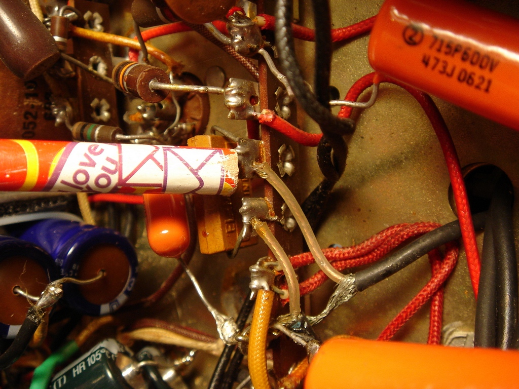
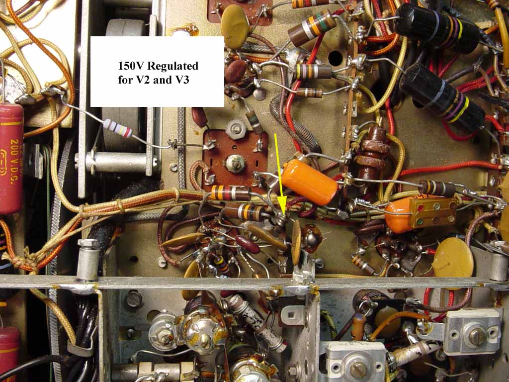
I chose not to restuff my Black Beauty caps; I simply replaced them all with Orange Drops. The Black Beauties are safely stored away for some time in the future when I, or another owner, may want to do the restuffing.

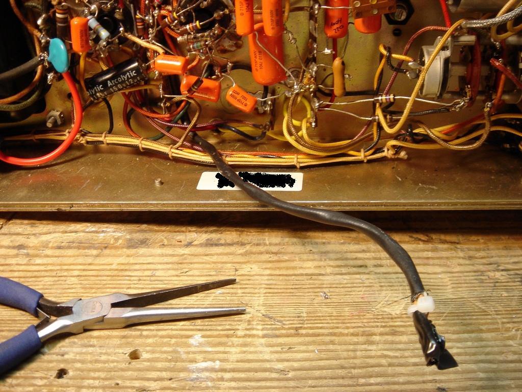
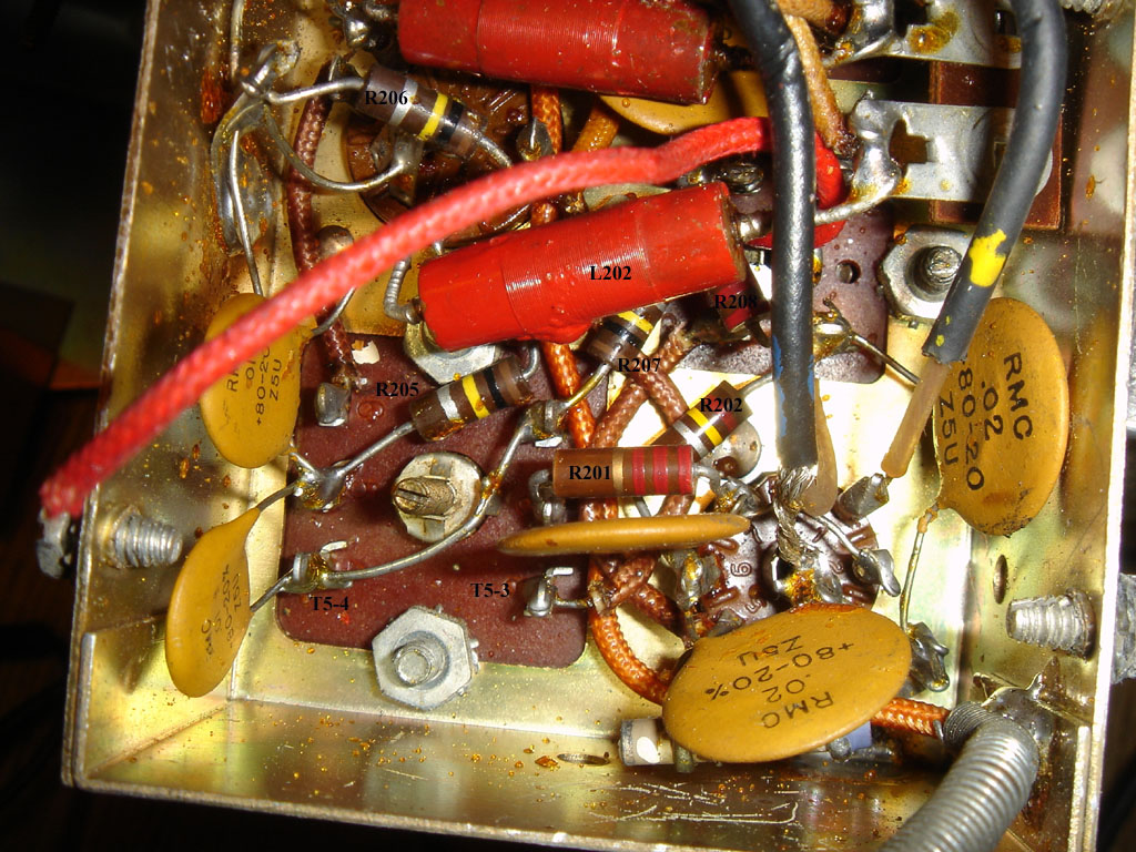
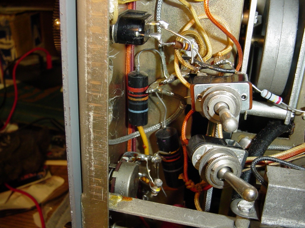
According to my manual there are 3 molded paper caps in the 2nd Converter sub-chassis (C208, C209, and C210 - 0.01 uF 600V). Replacing those caps can seem daunting at first because you need to lift the sub-chassis, but it's really not that bad.

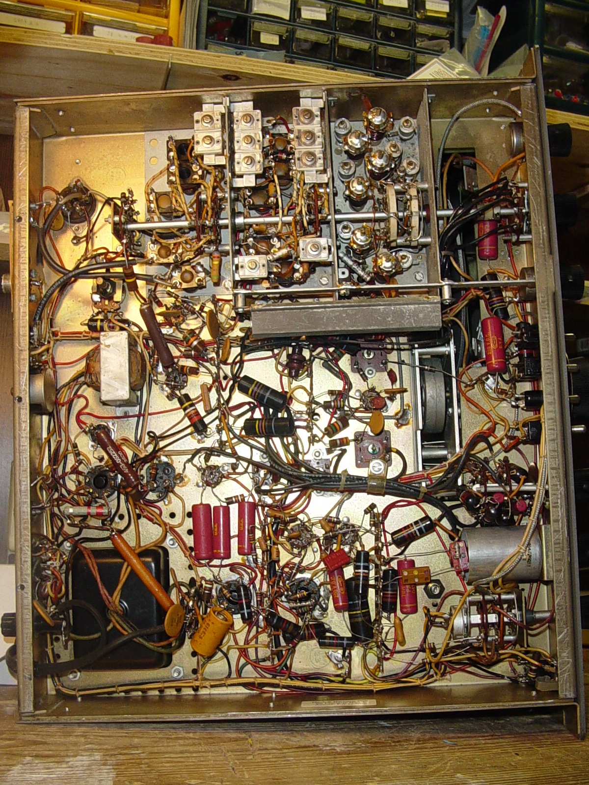
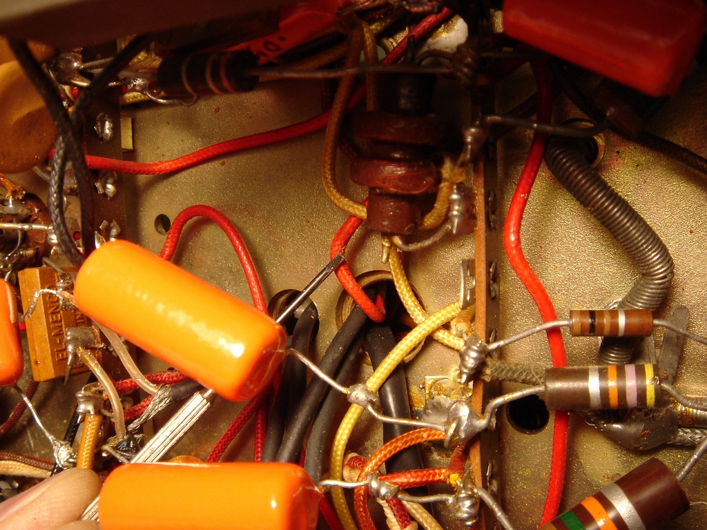
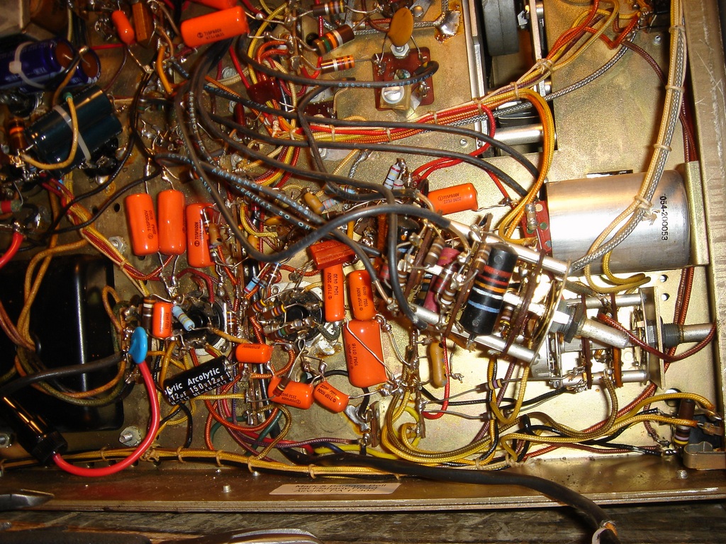
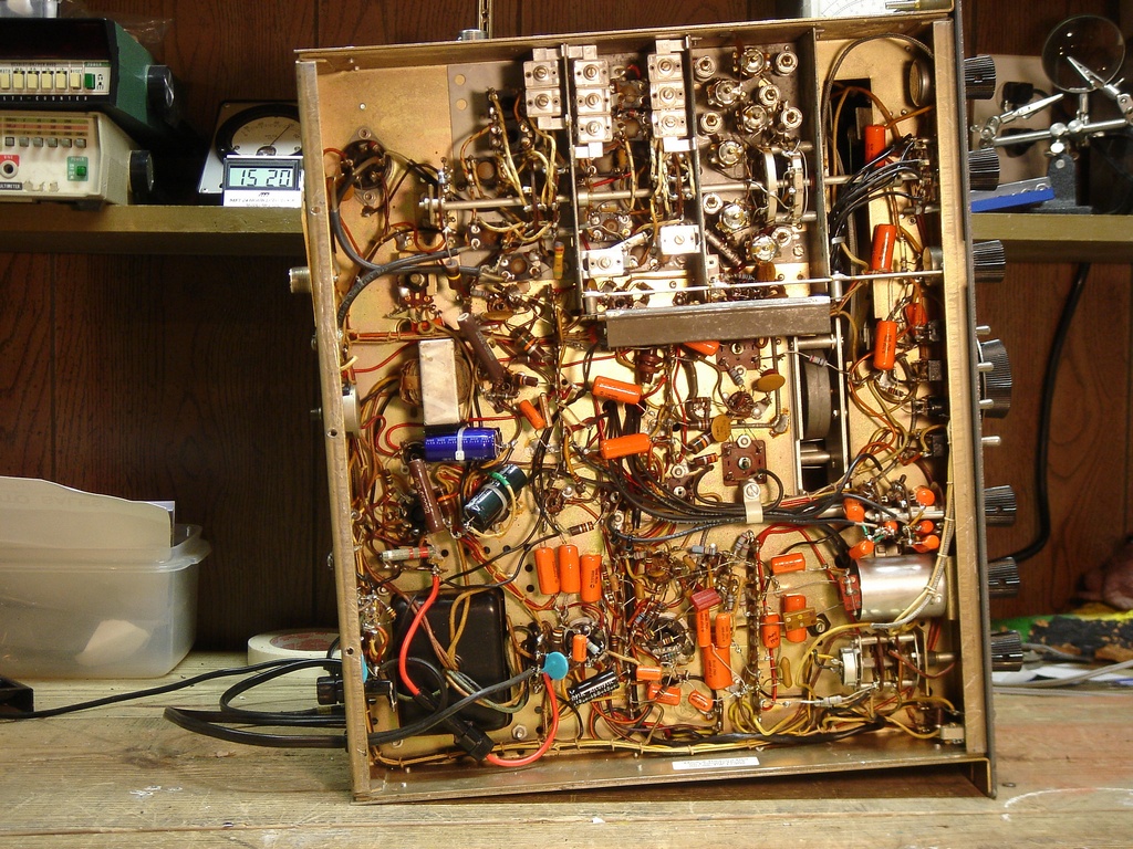
Here's the "unrecapped" SX-101A -- lots of Black Beauty of Death molded paper caps in there!


Underchassis "Map":

There are 6 basic steps that you need to follow to be able to remove the sub-chassis. Here's a picture of the bottom of the SX-101A with annotations as to where each step is located:


Step 1:

Disconnect the coaxial cable from T2 pins 1 and 6.


Step 2:

Unsolder the orange wire connected to V4 pin 4. At the ninety degree bend of the shield, note that the two (connected) sections of the shield are connected by a single wire. Snip the shield at the bend. Draw the orange wire away from pin 4 and through the part of shielding that is soldered to the chassis.

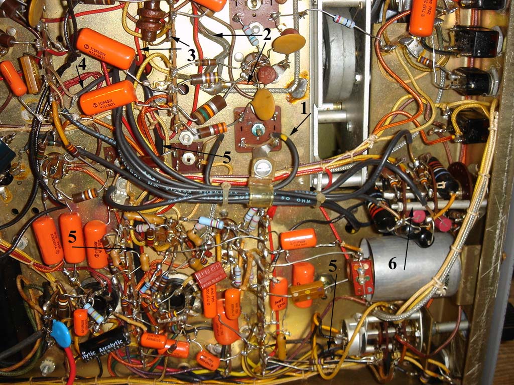
The shield is also soldered to the chassis inside the converter subchassis, but you do not need to worry about that.


Step 3:

Disconnect this orange wire from the terminal strip. Use a heat sink to prevent damage to the choke.


Step 4:

Unsolder the center wire of this piece of coax; clip the shield as close to it's solder lug as possible.


Step 5:

This is the thick black wire that really contains 2 wires carrying the 150V regulated to the subchassis. Carefully follow this back to the Response Switch and disconnect both wires.


Step 6:

Remove the Selectivity Switch and cut the cable ties so you can have some slack on the coaxial cables. Now's a real good time to replace all those Black Beauty caps and out of tolerance resistors on the switch - it does make a difference!


Remove the sub-chassis.

Unscrew the sub-chassis and carefully lift it off the main chassis while carefully feeding the wires you just cut through the holes in the main chassis.


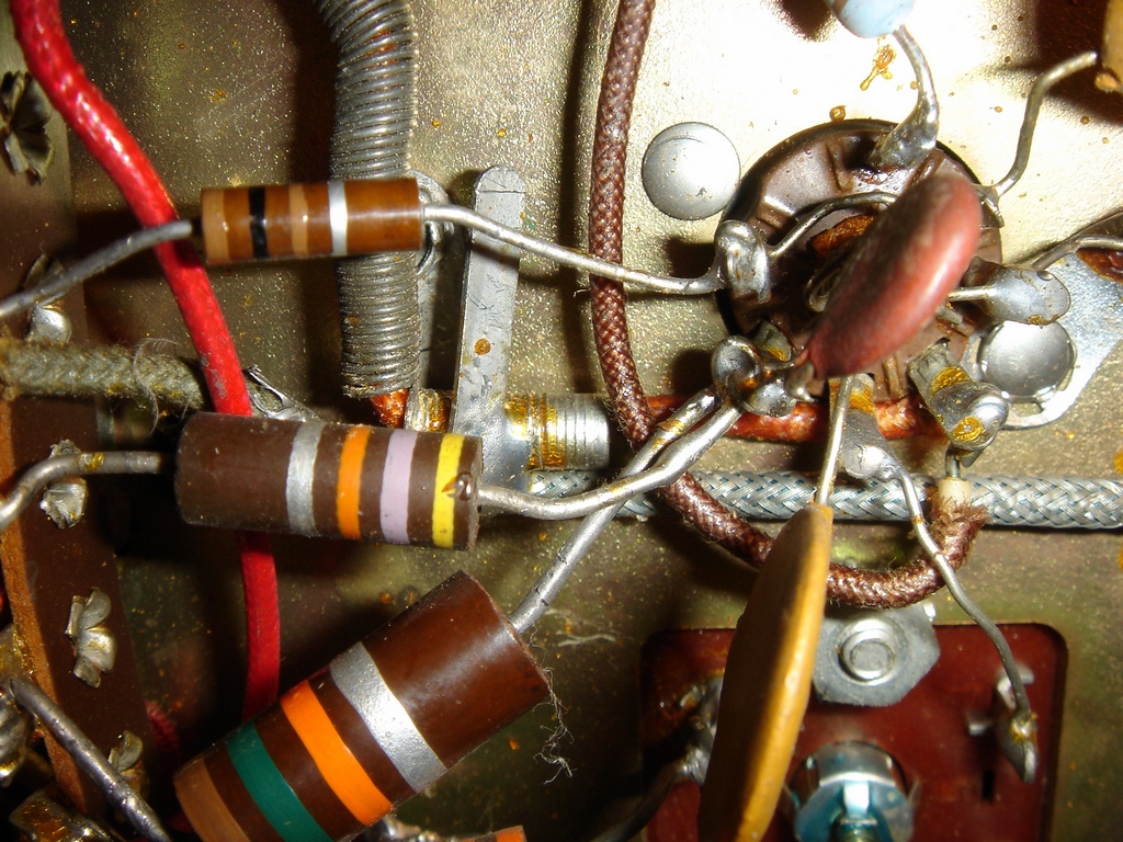
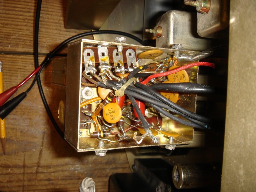
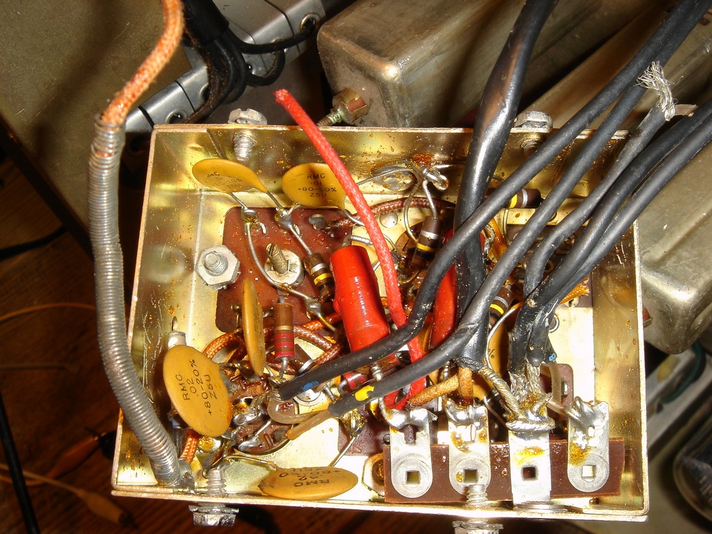
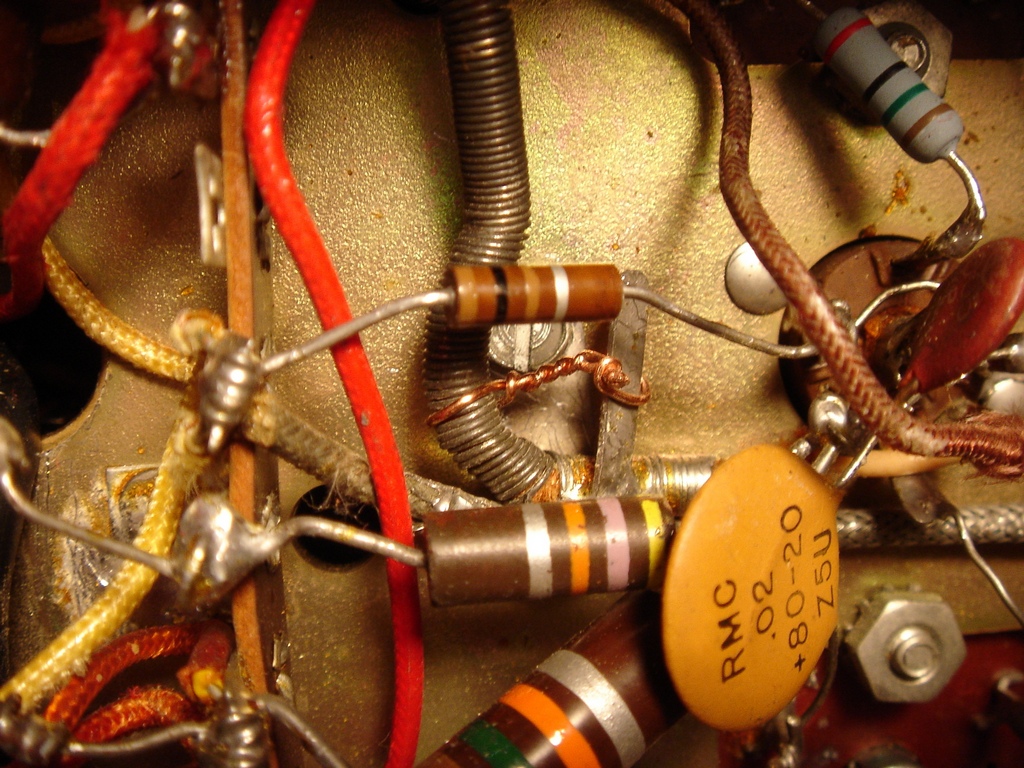
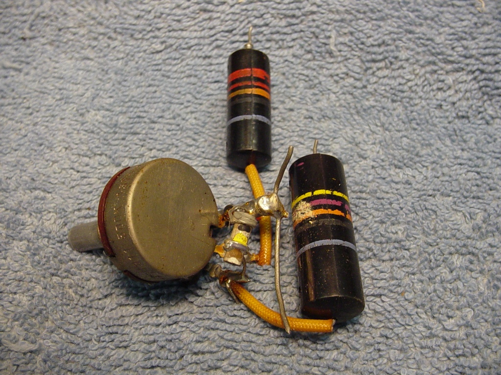
So, where are the Black Beauties? The answer is -- they're not there! Apparently, Hallicrafters changed their parts list at some point during 101A production, and substituted disk ceramic caps! Once I saw that I remembered my SX-101A manual is a copy and did not originally come with the manual.

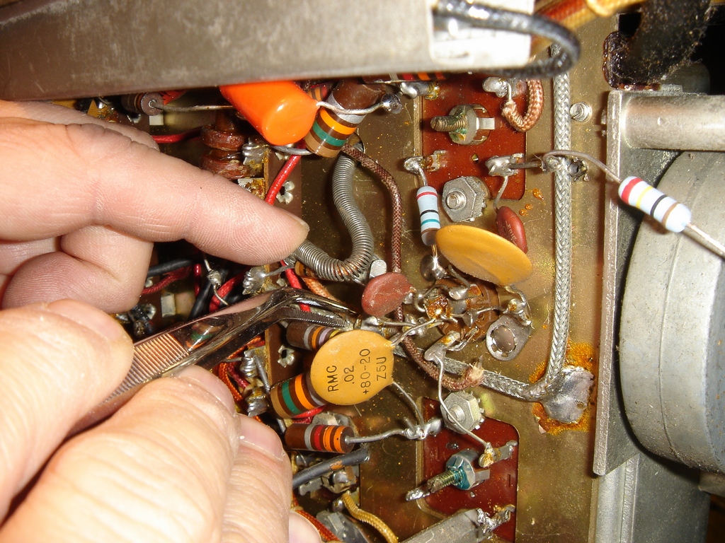
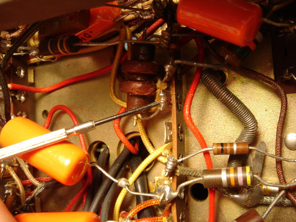
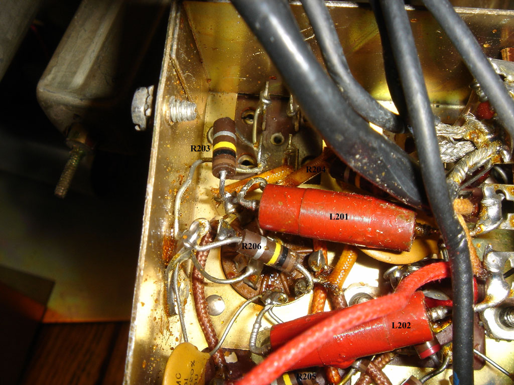
Well, while you're in there, test those resistors....

Replace the sub-chassis.

Replace the sub-chassis in the reverse order. I reattached the orange wire connected to V4 pin 4 as follows:


Done!


Here's a few other photos I took...


Copyright (c) Mark S. Bell 2010