K3MSB

TBW-4


TBW-4 IF Transmitter, Rectifier Modulator Unit, HF Transmitter

======================

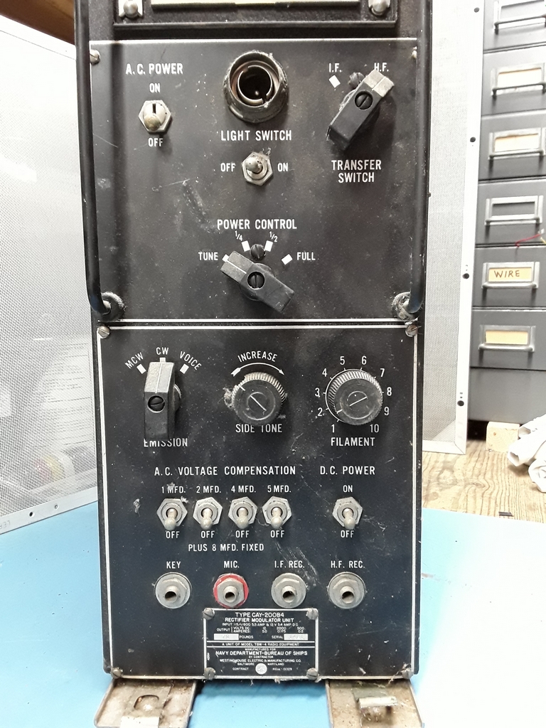
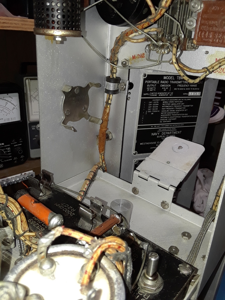
TBW-4 Rectifier Modulator Unit and HF Transmitter

--


The Trip to get the Rectifier Modulator Unit and HF Transmitter

As mentioned in my write up of the TBW-5 transmitter elsewhere on my website, I was looking for an 803 tube socket when Mike Everette WA4DLF contacted me and said he had a TBW-4 and Rectifier Modulator Unit available and asked if I was interested. And, by the way, the TBW was in a transit case! Mike lives in Raleigh NC and that's a day trip for me!

After ironing out the details I made plans to visit Mike a few weeks later in May. Unfortunately, the week before, terrorists shut down the Colonial Pipeline and there was almost no fuel to be obtained in the eastern NC area. I really wanted to make the trip and was looking for a way to do it with the fuel crisis. I figured if I refueled in mid Virginia I could get to Mike's place, load, and get back to mid Virginia with my "IFR Reserve" fuel still in the tank. Well, after thinking about this sanity prevailed and I canceled the trip.

Summer being a busy time, Mike and I could not connect until August. My wife and I finally drove down to pickup the TBW the first week of August. Mike is moving and his old house has been used as a storage area. Lots of boxes as you'd expect and I understood why Mike suggested I bring a dolly! Space in the basement was "limited" and of course the TBW was "way back there"! We used the time tested method of moving boxes to make room for boxes, then moving those boxes to get to the radios. Standard fare for those that restore old radios! It took Mike and I longer than expected but we "got 'er done".

The TBW and Rectifier Modulator Unit are in excellent condition and I asked Mike if he knew the history of the units. Mike replied: "I found them at the Shelby NC hamfest in 1974 if my memory serves me and they followed me home. It was one of "those" moments of nostalgia prompted by my having had fun with my first TBW-4 back in high school. Unfortunately I never got around to putting the second one on the air, other than using the antenna tuning network with an SSB transceiver (Hallicrafters SR-150) to load a 100-foot end fed wire. That worked very well."


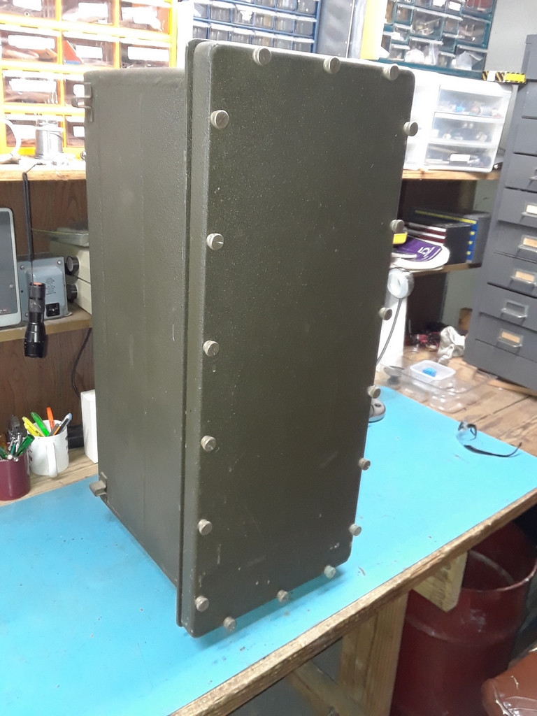
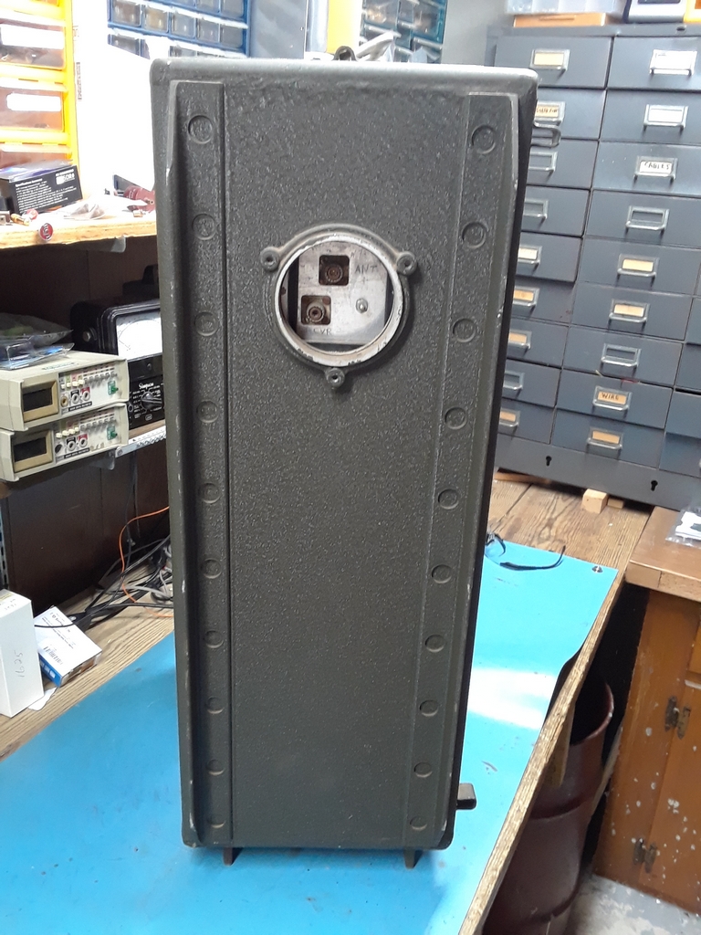
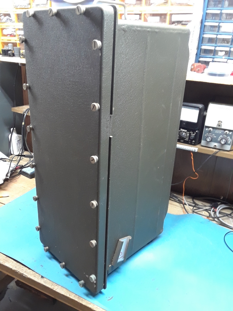
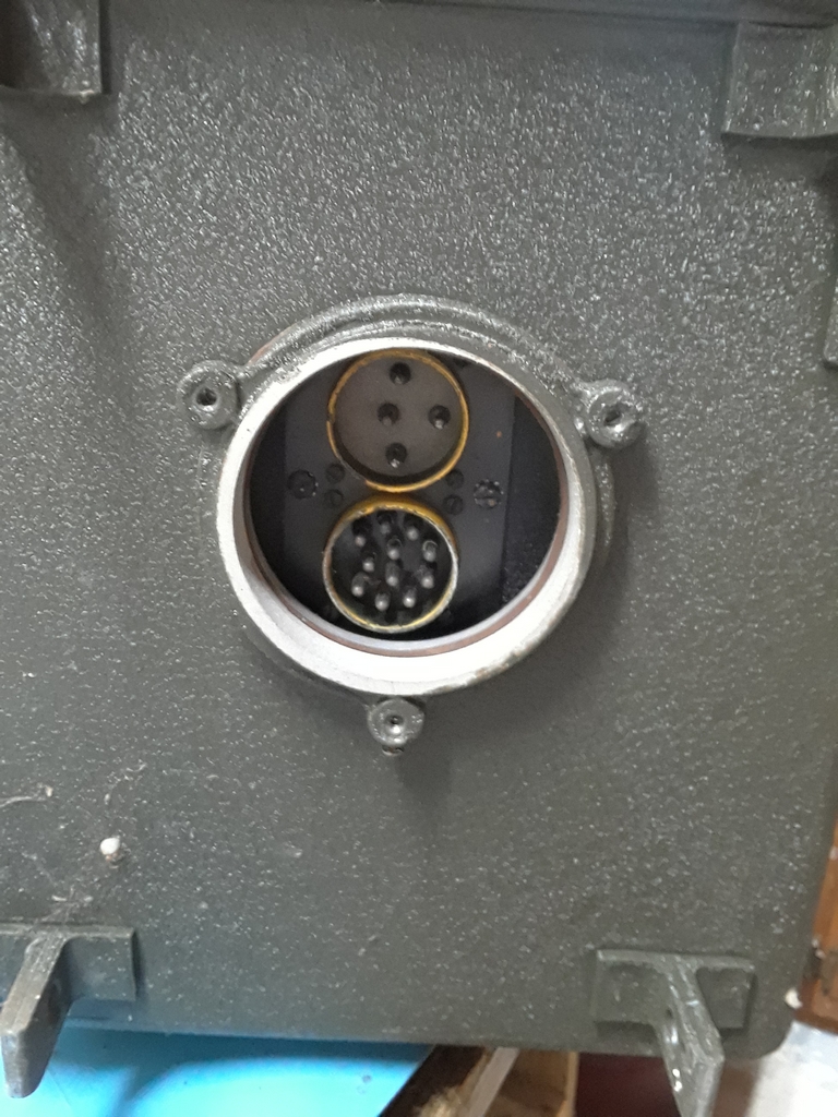
HF Transmitter Transit Case

-- -- --

-- --


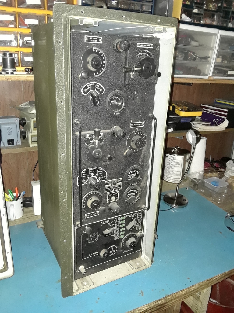
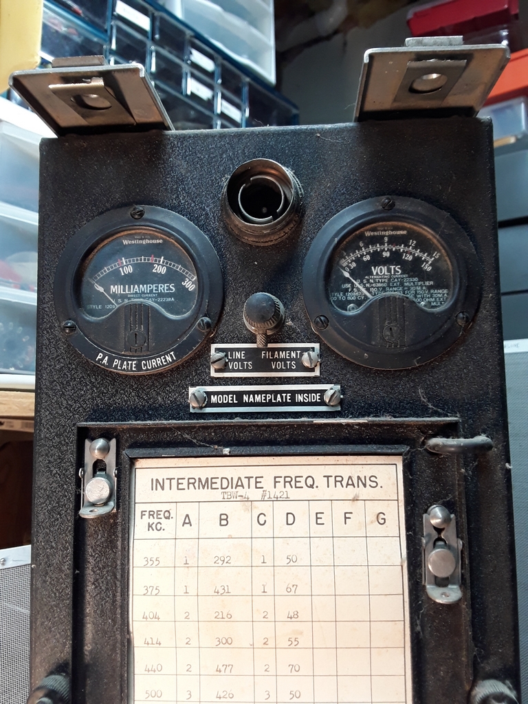
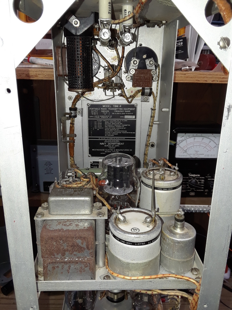
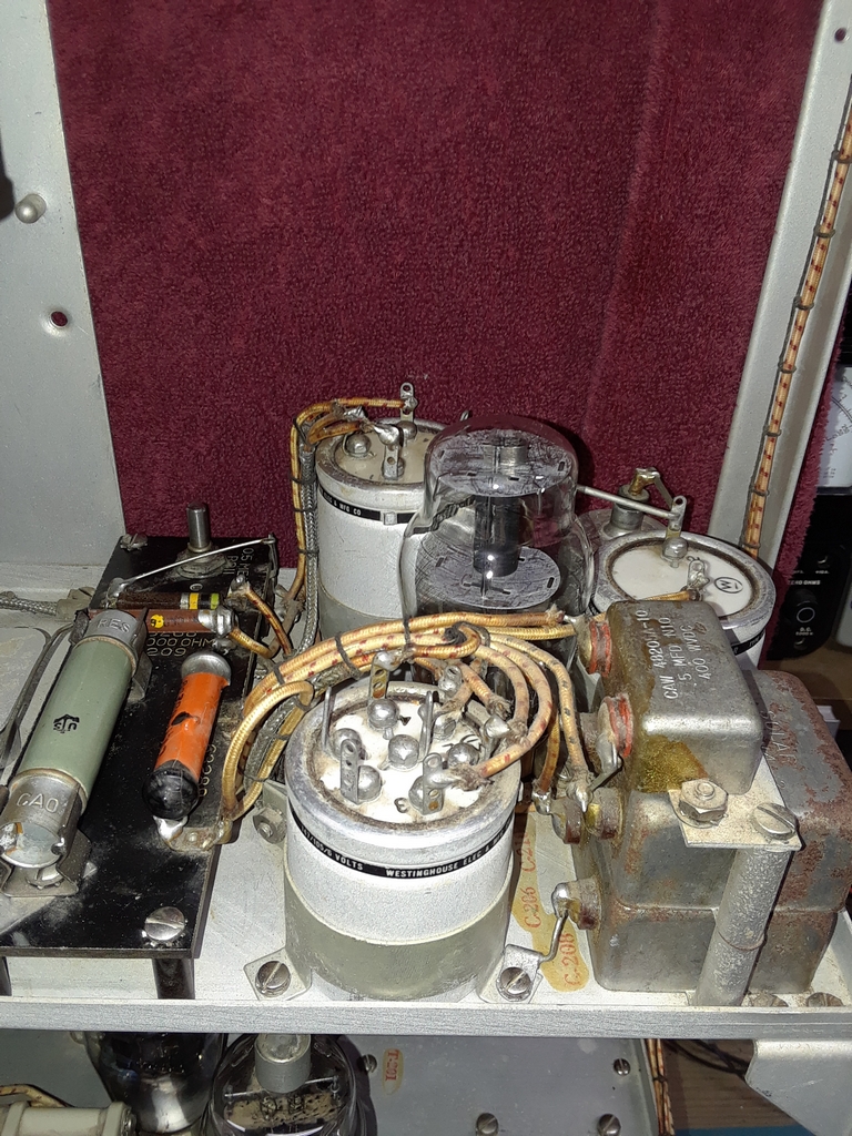
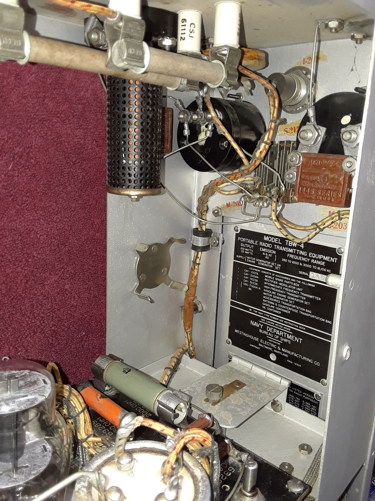
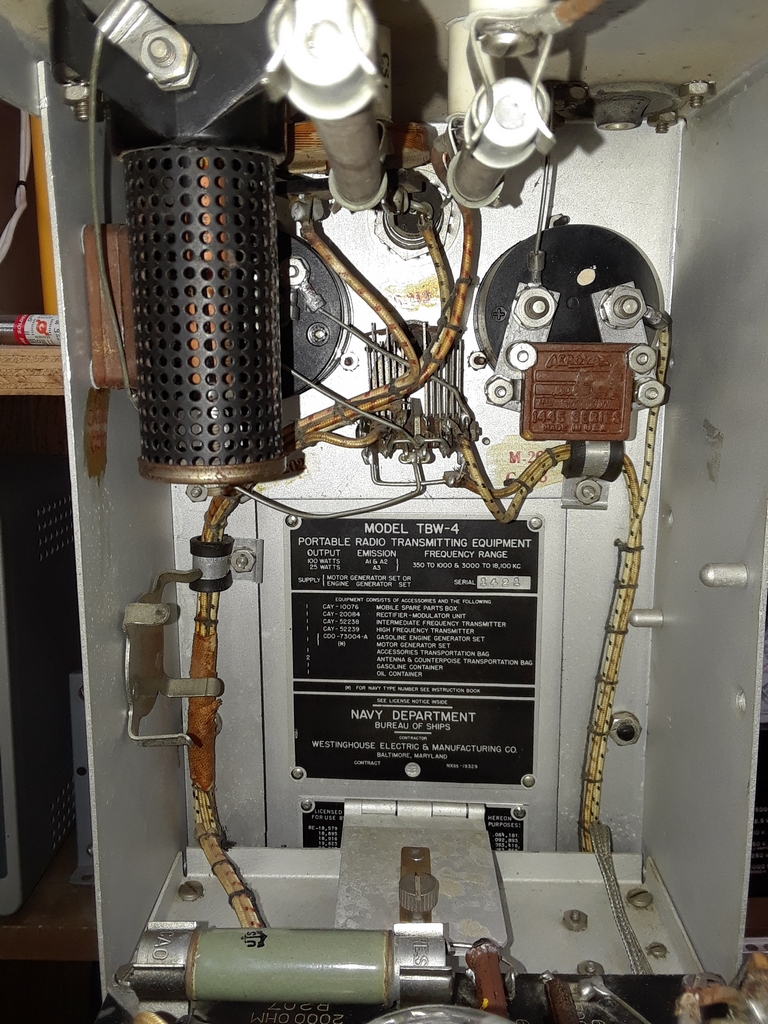
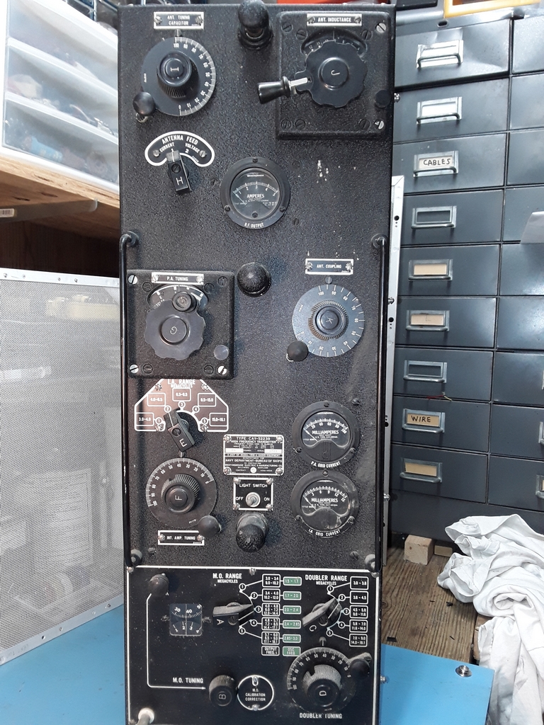
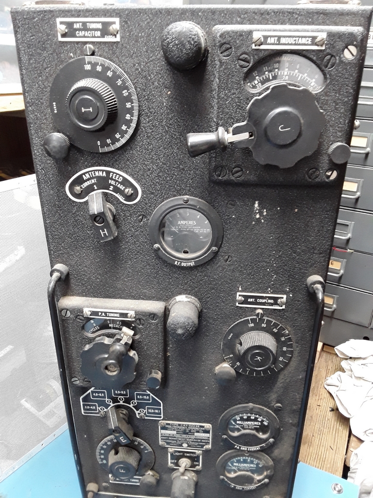
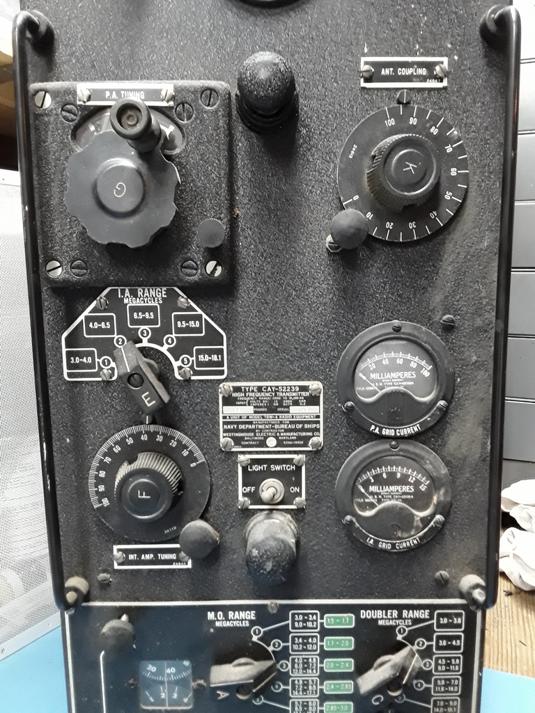
TBW-4 HF Transmitter

-- --

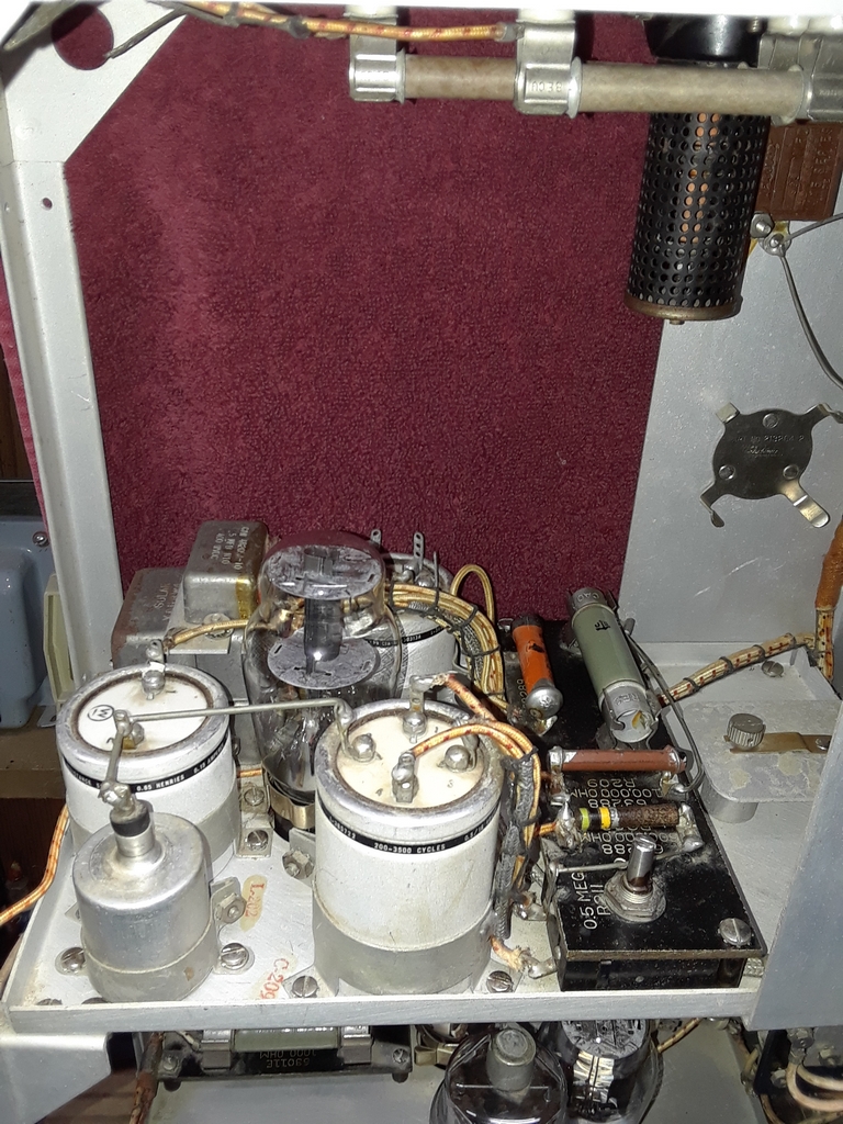
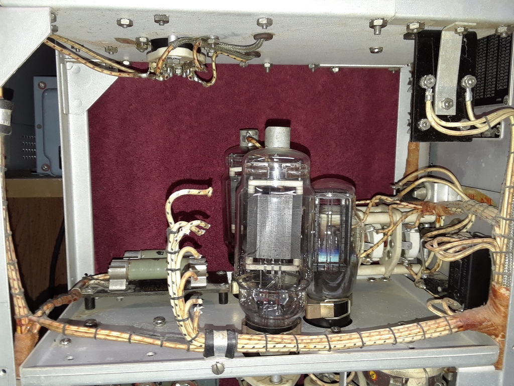
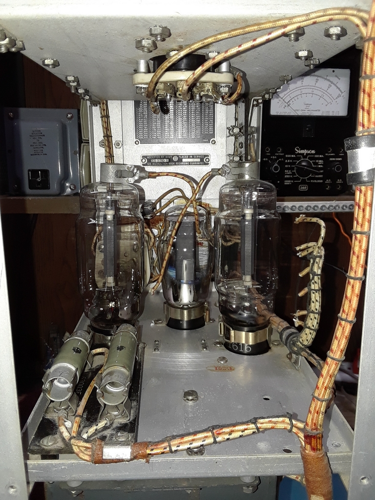
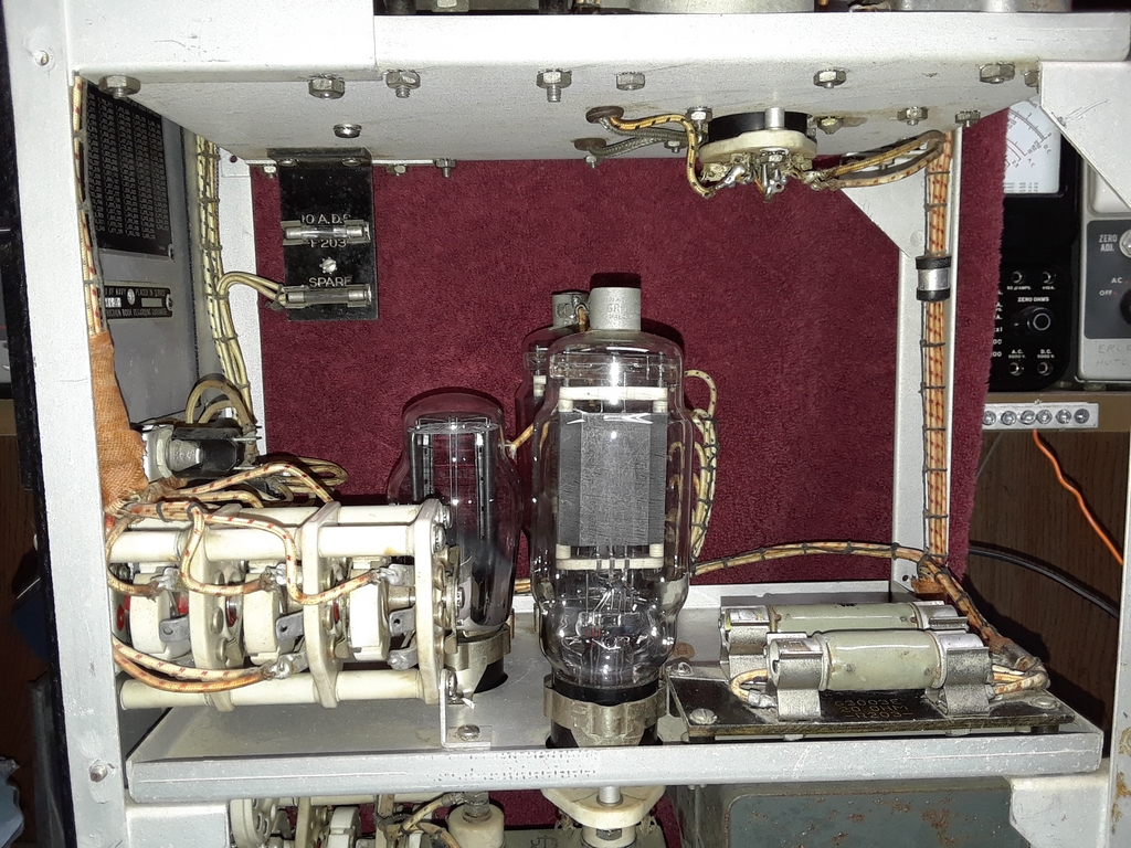
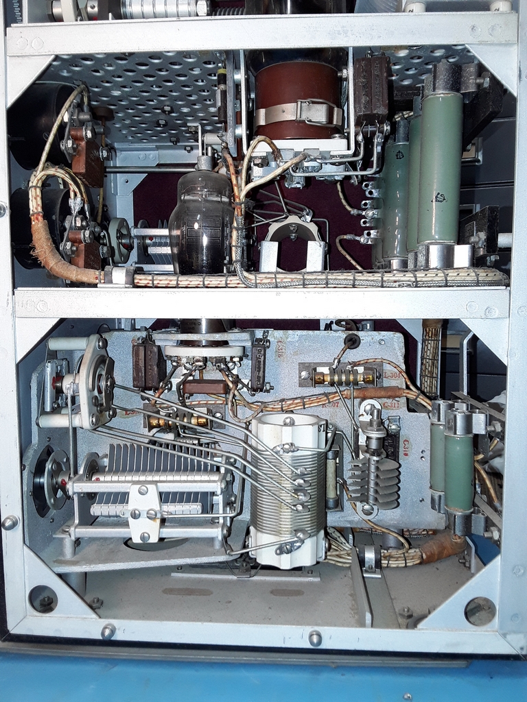
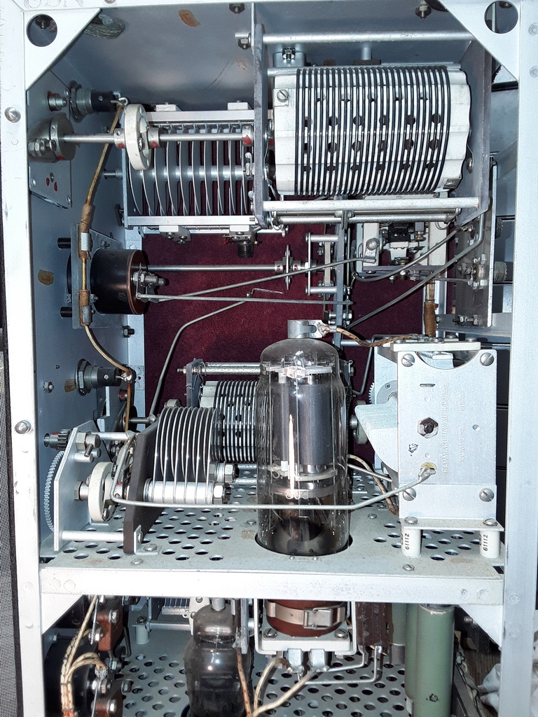
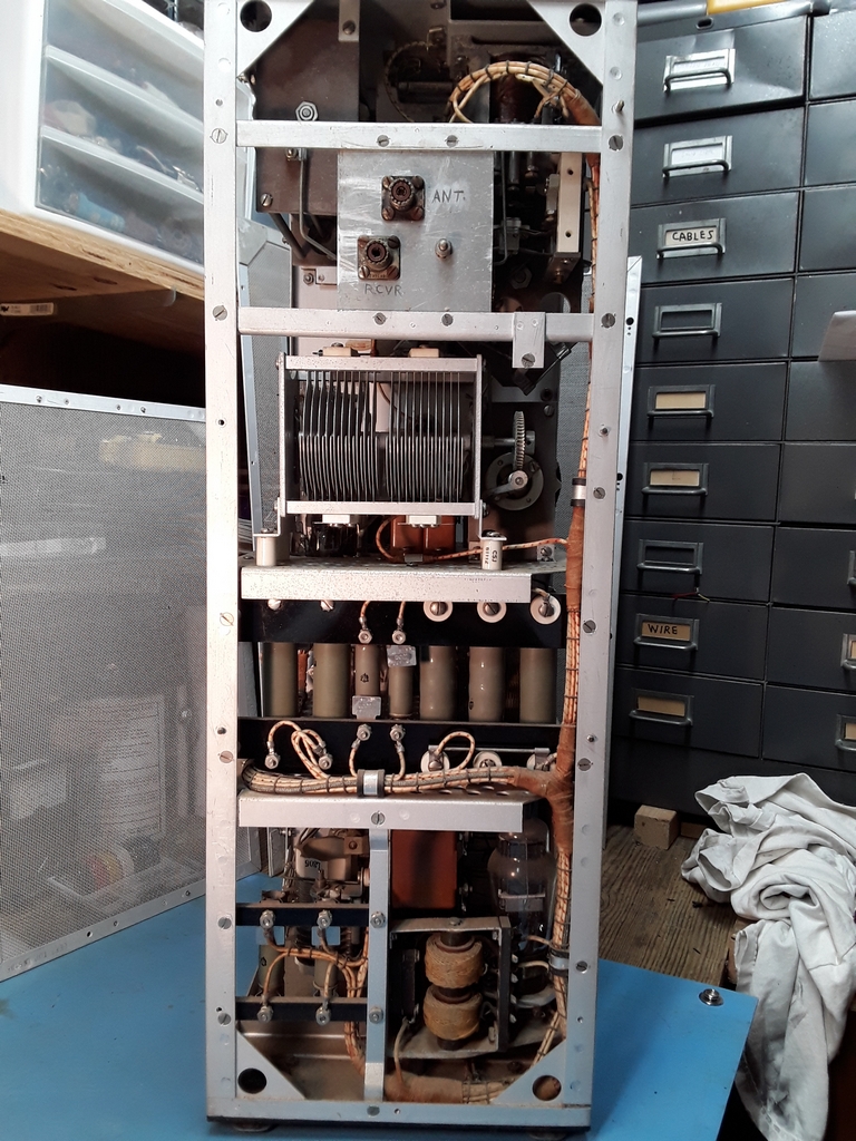
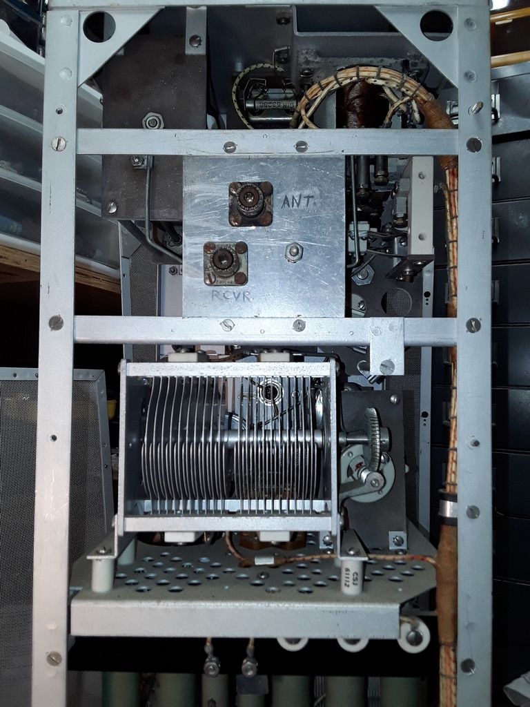
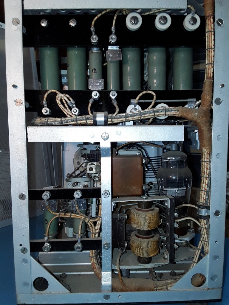
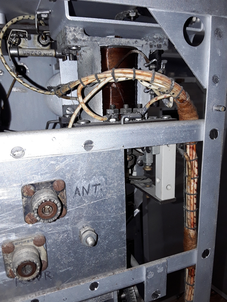
The TBW-4 is in clean and stock condition. There is nothing missing! Mike did a slight rewire of the output circuit to act as a tuner for another transmitter, and this can be seen by the extra SO-239 hanging off the capacitor in the upper deck. The original disconnected wire was just moved out of the way and it will be easy to remove this modification.
-- --

-- --

-- --

-- --

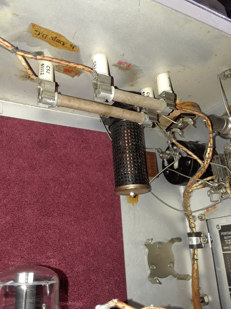
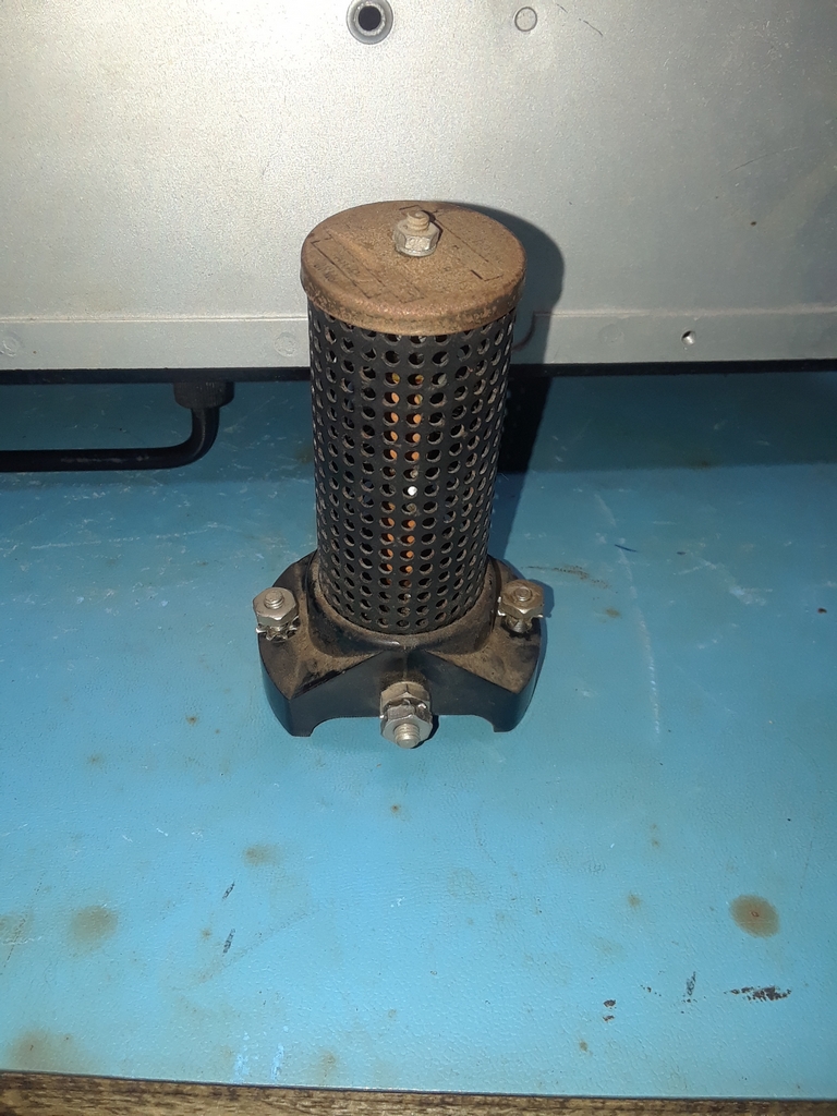
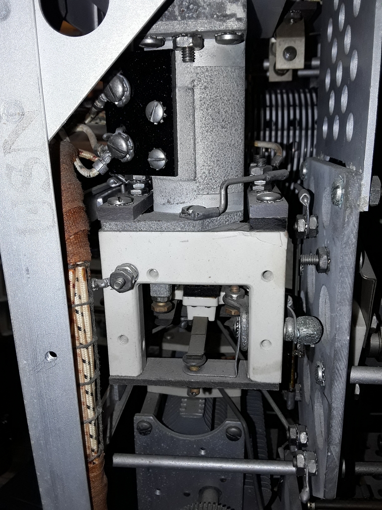
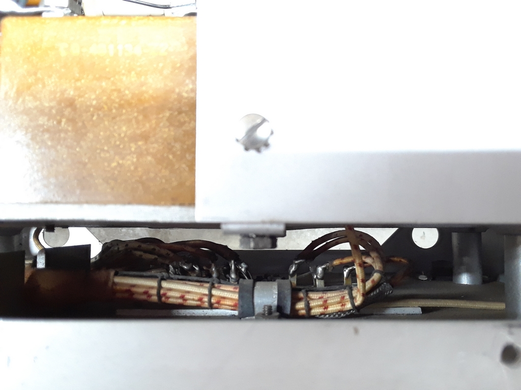
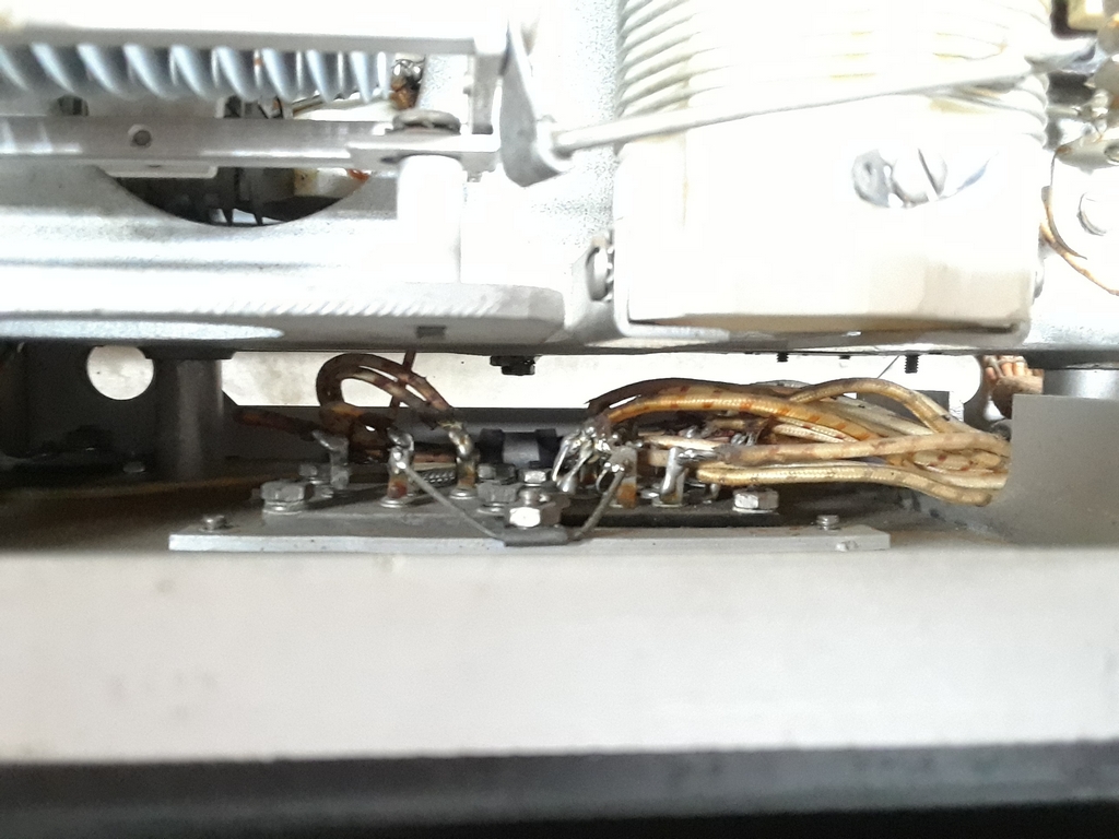
The following three photos are of relay K-301. This relay opened and closed in sequence with your keying!
-- --

Listen here!


-- -- --


TBW-4 Rectifier Modulator Unit

The RMU was stored without a transit case so it will require some cleanup. What I was delighted to find was that it is also in stock condition and only missing the HV and Filament transformers. Since these are 800Hz transformers, that is not significant for me.
-- -- --

Having the RMU is important for a realistic restoration for a couple of reasons. First, the plate current meter is the top left meter (center photo above). Second, the Emission switch, mic, and key jacks are at the bottom of the unit (below left photo).

Note also in the above center photo the dual line voltage / PA Filament voltage meter. This is an 800 Hz meter and testing has shown it's pretty accurate at 60 Hz.

--
The plate that holds the frequency card is actually a swinging door that opens to access the area where the mic and key are kept. The 4 pronged round clip held the RS-38 hand mic made by Telephonics Corporation. The hinged metal plate flips down for straight key storage.
-- -- --


RMU Upper Deck

The three photos below show the modulator components. In the center photo, input transformer T-205 is to the right of the 843 Modulator Tube while Modulation Transformer T-204 is to its left.
-- --

More photos of the upper deck. The meter on the left is for the dual line voltage / PA filament voltage and the meter on the right is for plate current. Note the fuses on the roof of the top deck.

The large cage behind the line voltage / PA filament voltage meter is R-206, the meter multiplier resistor used when measuring the line voltage.
-- -- --
Those large "resistors" that can be seen hanging from the top of roof of the RMU are not resistors! The are fuses F-201 and F-202. F-201 (3/8A 1 KV) is after the 500V filter stage and F-202 (1/2A 2.5KV) is after the 2KV filter capacitor.
-- -- --

-- --


RMU Middle Deck

As can be seen in the left and center photos below, the Main Plate Transformer T-201 is missing. The output of T-201 fed the two large 1616 High Voltage Rectifiers which provided 2KV to the plate of the 803 PA tube.

The smaller tube on the middle deck is the 5Z3 "Aux" rectifier. This is fed by the Low Plate Transformer T-203 which is (still) on the lower deck. The output of the 5Z3 provides 500V to the modulator circuit on the upper deck as well as the bias network in the transmitter.

In the right hand photo, the large switch is the "Transfer Switch". This selected either the Intermediate or HF transmitter and routed the 2KV and 500V lines, as well as the modulator output, to the selected transmitter.
-- --


RMU Lower Deck

The black transformer is the Low Plate Transformer T-203 which feeds the 5Z3 as discussed above. In the empty space next to it would be the Filament Transformer T-202.

The large capacitor above T-203 (left photo) is the "Compensation Capacitor" C-201. There are four capacitors inside this unit and they can be selected (in any combination) by the four "AC Voltage Compensation" switches on the lower from panel of the RMU. As stated in the manual C-201 "is used to correct the power factor of the circuit so as to prevent undue fluctuation of the filament voltage when the transmitter is keyed." As originally used, the transmitter was keyed by keying the primaries of the Main Plate transformer T-201 and the Low Plate transformer T-203 via relay K-301A in the HF transmitter. C-201 and the associated front panel selection switches were used to ensure stable filament voltages as those transformers were keyed and unkeyed.

The large switch in the left photo is the Emission switch. For "Voice", the output of the modulation transformer T-204 and the bias voltage via R-205 are supplied to the suppressor grid of the 803 PA tube. For CW, the suppressor grid of the 803 is grounded. For "MCW" an 800 Hz tone (obtained from a secondary on the Low Plate Transformer T-203) is applied to the suppressor grid.
--
-- --

======================

TBW-4 IF Transmitter


The early part of January 2023 found me once again traveling to North Carolina to acquire another piece for my TBW restoration.

This time my good friend Brad KO3T (on the right in the photo) accompanied me. We had a nice visit with Joel Walker in Roxboro NC from whom I picked up the IF Transmitter.

Joel said he had the IF Transmitter since the early 1980's and had not touched it. The transmitter did suffer some damage from a previous owner and from a leaky capacitor. Fortunately, the damage looks to be straight forward to fix.

I found it rather interesting to note that while we were on our way to pick up a radio built over 80 years ago, Brad was in the passenger seat on his Tablet computer, hot-spotted into his phone, and remotely logged into our club station trying to work some DX on 12M FT8 !!

Right Side Views

-- --
-- --


Rear Views

-- -- --


Left Side Views

-- -- --
These photos shows the damage to the transmitter. C101 is attached to the roof of the transmitter and has been leaking for some time. It has leaked onto L109 and has damaged the coil form. Fortunately, there does not appear to be any damage to the wiring.

The wires to the left of variometer L109 are for C-124 (I think...) which is missing. This is a 0.005 uF 3 KV Mica capacitor.

Note that the 807 Intermediate Amplifier Tube is missing! When I initially saw the radio the 807 was in a socket sitting unsecured to the frame with all the socket wires cut! The socket was not from the TBW and it was corroded with the base of the 807. The socket wiring is there and unharmed. I have no idea what a previous owner had in mind.


--


Bottom View

Copyright (c) Mark S. Bell 2021