The Trip
|
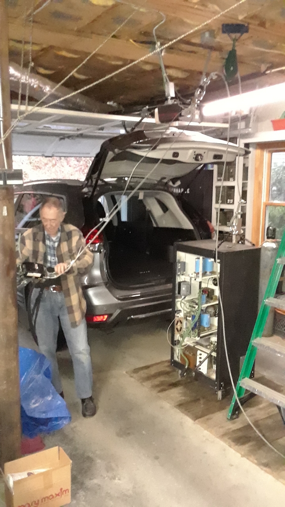
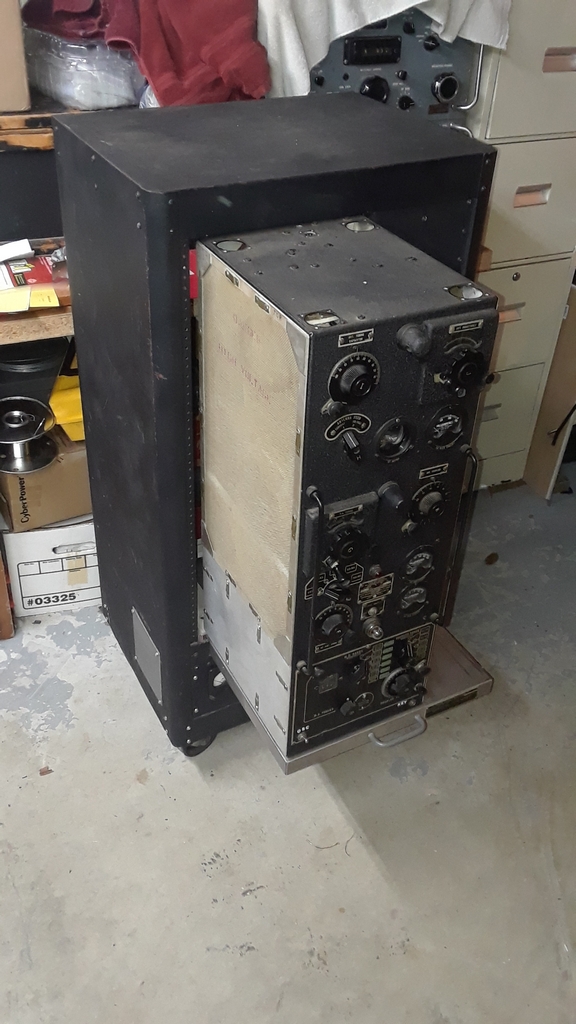
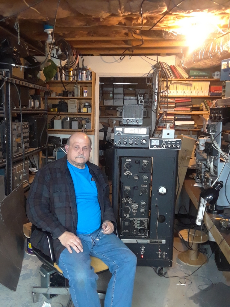
My wife and I drove down to Lakemont GA in October 2019 to meet Bob Lackey and his wife and to pick up my "new" TBW transmitter. Bob and his wife were gracious hosts on that rainy Saturday morning, and the wives talked about things wives talk about when their husbands are doing important radio work.
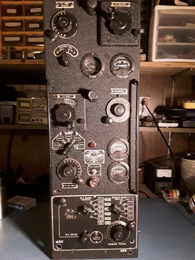
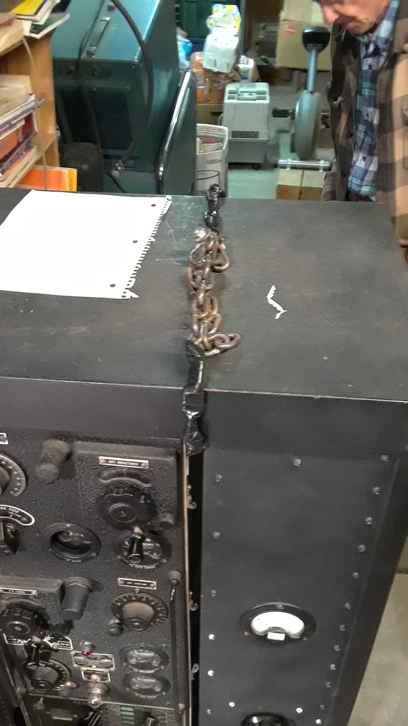
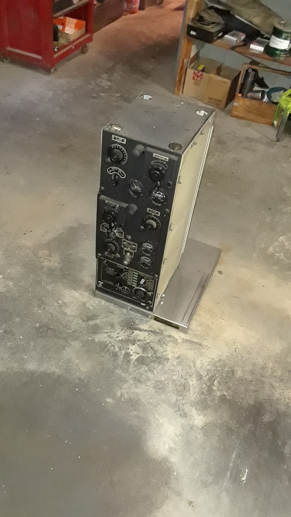
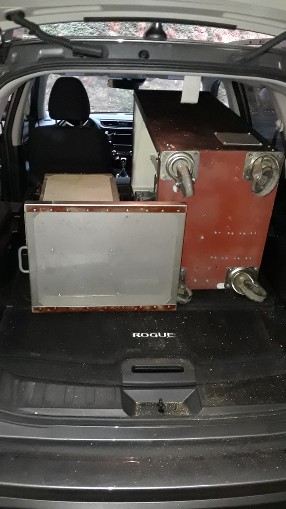
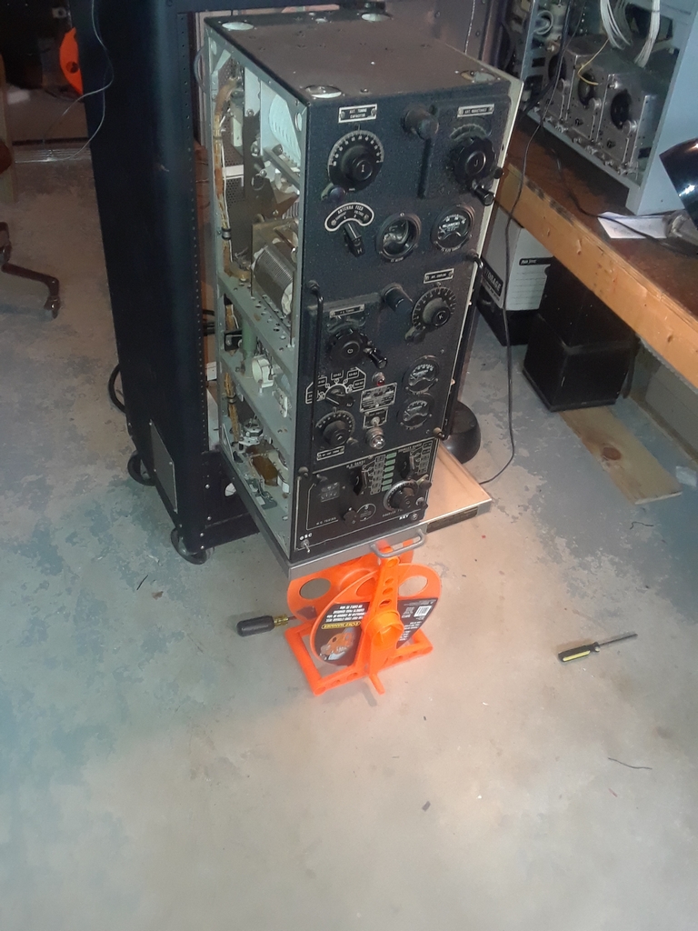
The two left photos show the TBW in Bob's shack with Bob W4QBE in the leftmost photo. The transmitter is housed in a home-brewed rollable power supply that Bob built after he got the radio. Bob acquired the transmitter from Steve Finelli N3NNG of Easton PA in September 2000 while attending the MRCA meet. It was not lost on me that after almost 20 years the TBW has made a round trip journey to its new home in York PA that is just about 100 miles from Easton PA! Note the chain Bob had installed to help us get the transmitter and power supply into my car. The transmitter weights in at 88 pounds and the power supply weighs in at 160 pounds. When Bob built the power supply, he mounted the transmitter on a slide out desk panel for transmitter maintenance. For the trip, as shown in the two right photos, we removed the transmitter from the power supply. |
 --
--
 --
--
 --
--
 --
--
(Click for larger images)
|
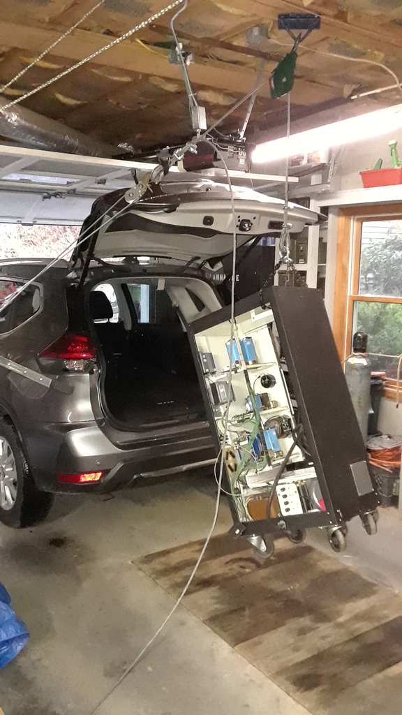
Bob already had a pully attached to a beam in his garage and a Come Along attached to a sturdy wally stud. Seeing what other goodies
Bob had in his shack, I'm not surprised at this. It was a good idea for the TBW, but only if you had a pickup truck. There was
no way we could get that power supply into the back of my SUV hoisted up like that. We lowered the power supply, put a rug over the end of the
hatch back, tilted the power supply over, and I lifted the back end and shoved it into the car (which wasn't as bad as it sounds). Afterwards, the transmitter
went in.
And finally, in the right Photo Bob W4QBE and Mark K3MSB. |
 --
--
 --
--
 --
--
 --
--
Back Home
|
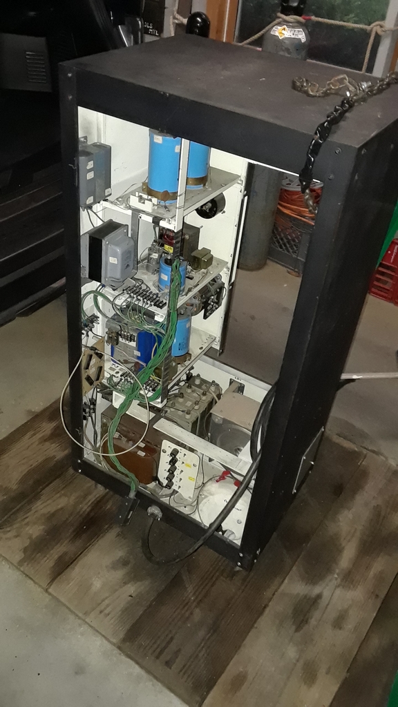
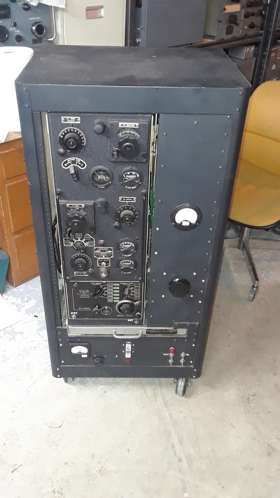
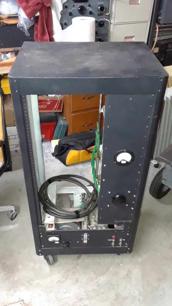
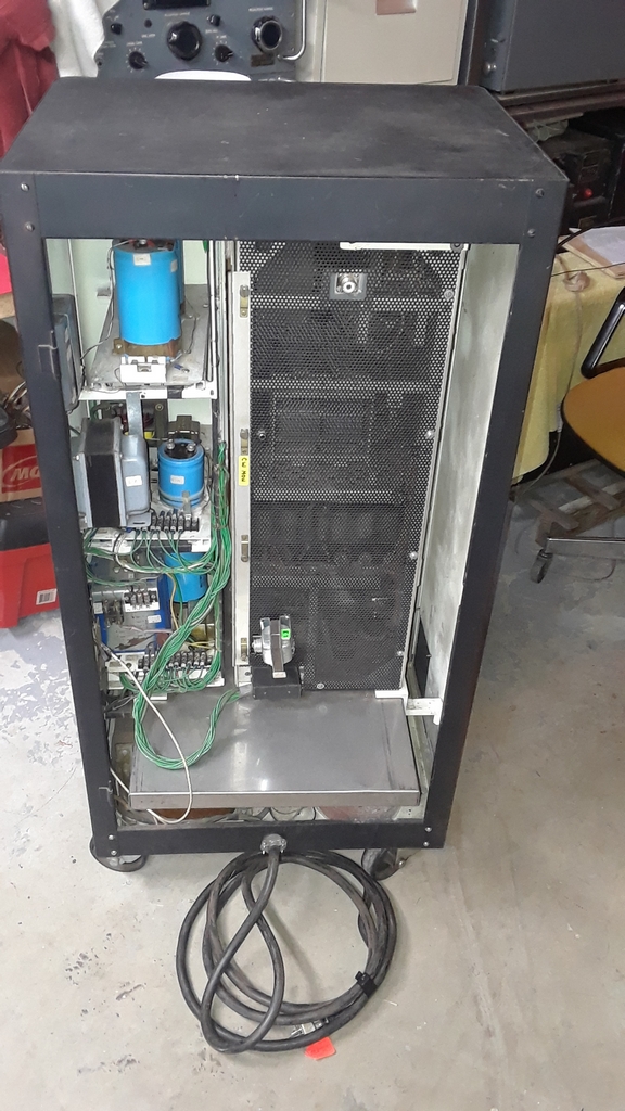
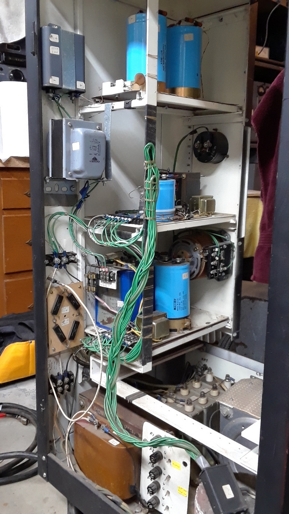
Here's some photos showing the construction of the power supply and how the TBW fits into it. The bottom of the unit houses the
803 Plate Power supply, and the rest of the power supply is for the 500V, bias, and numerous filament supplies.
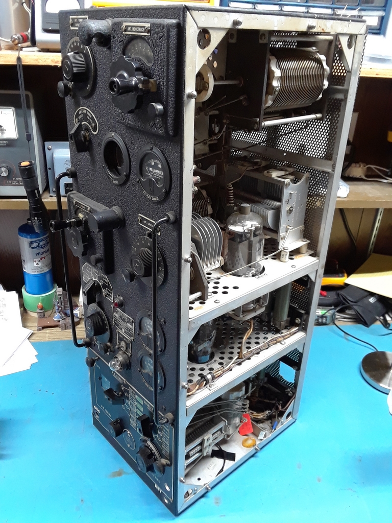
A complete TBW setup consists of a low frequency transmitter, a high frequency transmitter (like mine) and a rectifier modulator unit (RMU). All the power transformers were housed in the RMU which Bob did not have. It would not have made any difference if Bob did have the RMU as the TBW was intended to be run off of an 800 Hz gasoline generator. So, all the original power and filament transformers are 800 Hz. There have been attempts to run the 800 Hz transformers off of 60 Hz and they have all ended badly. In the photo showing the right side of the transmitter you can see where Bob replaced the 803 with an 813. |
 --
--
 --
--
 --
--
 --
--
 --
--
 --
--
 --
--
|
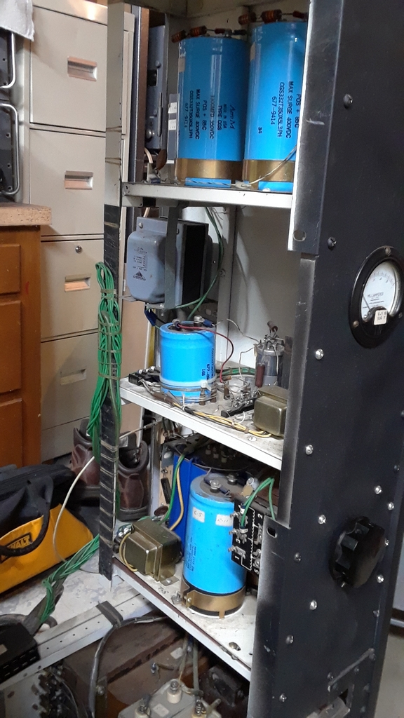
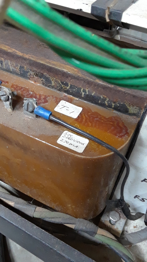
The left photo (below) shows the 813 Plate Transformer which is controlled by a monster variac in the lower part of the power supply. The output of
the transformer goes into a solid state bridge rectifier and then onto the capacitor input filter stage. As with the rest of the power supply, Bob generously fused everything!
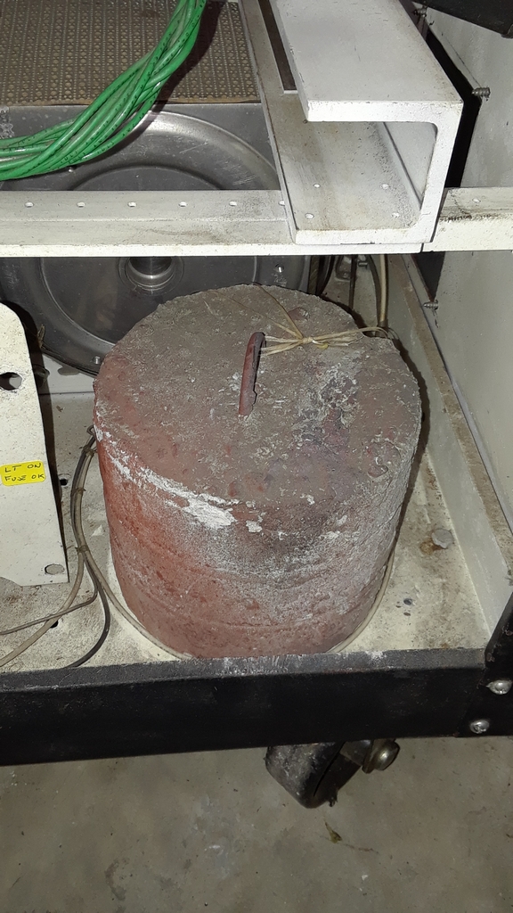
The right photo shows a concrete weight that must be in the power supply to balance the weight of the transmitter when it is fully extended on it's metal slide for maintenance. I wish I had thought about that weight, about 25 pounds, as I hoisted the power supply into my car! |
 --
--
 --
--
Getting the TBW ready.....
|
It takes some time to understand how to tune a TBW. I read the manual provided by Bob, but it still took a while to
really get comfortable with the tune-up. I was getting power out of the transmitter but the frequency was significantly
off from where it should be based upon the manual settings. I find that an SDR is an invaluable tool to troubleshoot problems such as
these. Not only was the frequency off, but I wasn't pleased with the keying waveform.
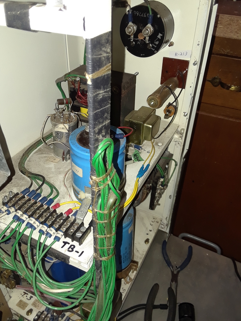
Bob had modified the TBW over the 20 years he owned the radio, and he provided me with about 6 different hand drawn schematics of the power supply and transmitter modifications. He said he didn't remember which was the latest so it was a bit of a challenge for me in the troubleshooting process. I saw a sticker for "R213" in the keying circuit, but the resistor was missing. R213 resides in the RMU, in the CT secondary of the oscillator filament transformer. With R213 missing I could see where the oscillator may have some issues. In the end, instead of adding R213 in the modified keying circuit, I removed all the keying and spotting circuits and added R213 to the power supply case (left photo below). I key the transmitter by grounding and ungrounding the grounded end of R213. The frequency is now much more close to the expected frequency, and the keying waveform is much better. Chirp. Yup, there's chirp, but that's due to poor regulation on the grid of the oscillator. Bob added a VR stage consisting of an OB2 and OA2 to address this, but voltage measurement still show a 30V to 40V difference between key up and key down. The chirp is a bit more than I'm comfortable with and I plan to replace the OB2 and OA2 with a zener string. Since I mainly operate the TBW during classic on the air events, nobody minds the chirp. |
 --
--
 --
--
| As I mentioned above there's a 25 pound cement weight in the bottom of the power supply to balance the TBW when fully extended on its slide out tray. It works nicely, but I always put something underneath the tray! |
On the air!
|
As we're all aware, 2020 was a stressful year, and it delayed me working on the TBW. But, the TBW-5 maid it maiden voyage on
80M on Sunday March 28, 2021 during the Classic Exchange (CX) radio event!. I made a total of 22 QSOs during that evening with the TBW,
and received four RSTs with the hallowed "C" attached. One of those QSOs was a rather special one.
Howie WB2AWQ/7 has been my sounding board for the TBW-5 work. He worked me with his GO-9 that night! A transcontinental GO-9 to TBW QSO!! |
 --
--
 --
--
 --
--
|
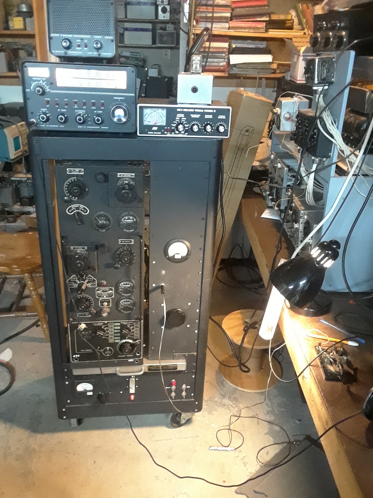
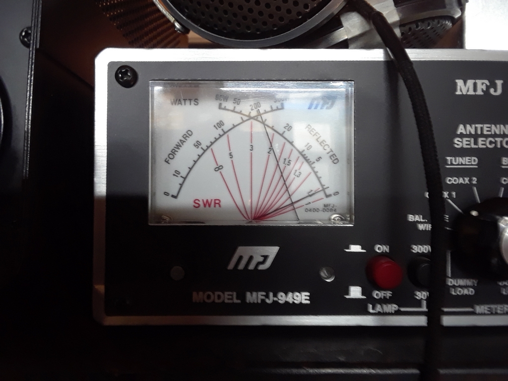
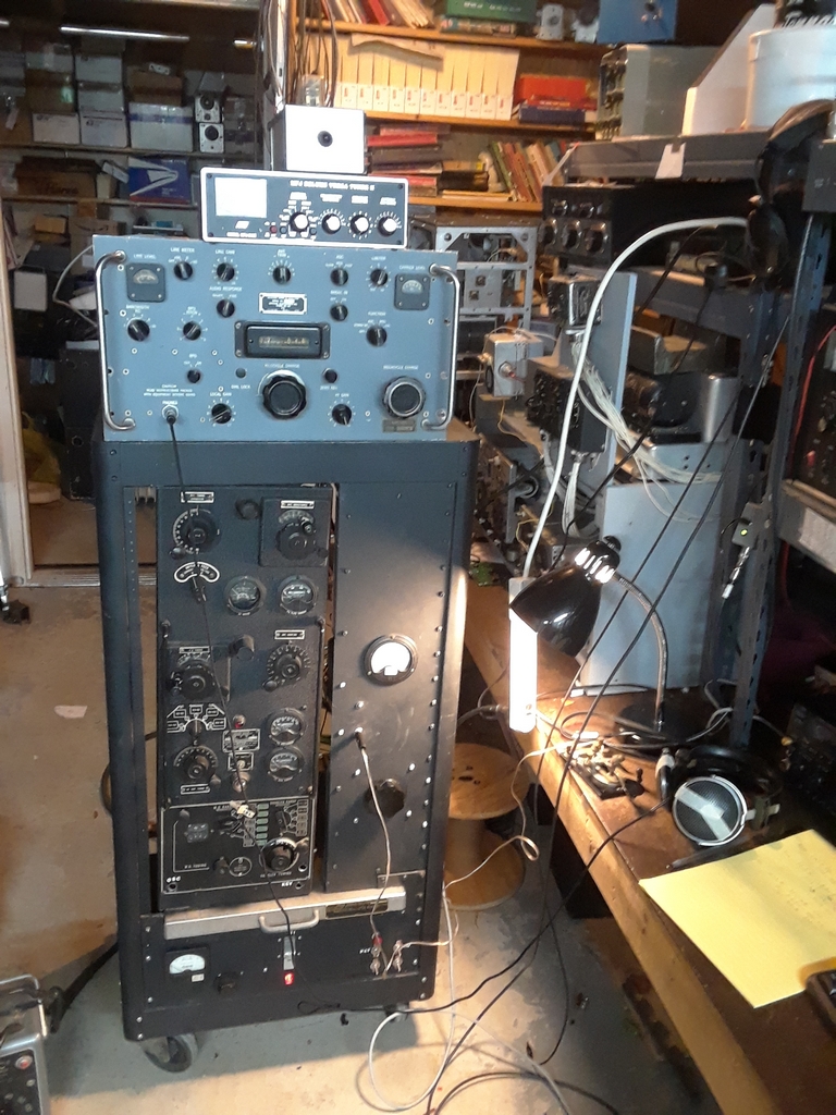
The above left photo shows my current TBW setup. I have it paired with my Drake 2B/2BQ. The small metal box on top of the MFJ tuner
is a homebrew TR box (manual switching). The real TBW setup uses a pair of RBM receivers. I have two RBMs and they are "in the queue".
The astute reader will note that the TBW controls are different in the above two left photos. The one on the left is when the transmitter is tuned for 20M. The two on the right are for 80M. I was just getting a bit over 200W out, and that probably corresponded to a plate voltage of just north of 1200V. Normally I just run reduce plate voltage so I get between 100W and 125W out (which is plenty for causal work). |
 --
--
 --
--
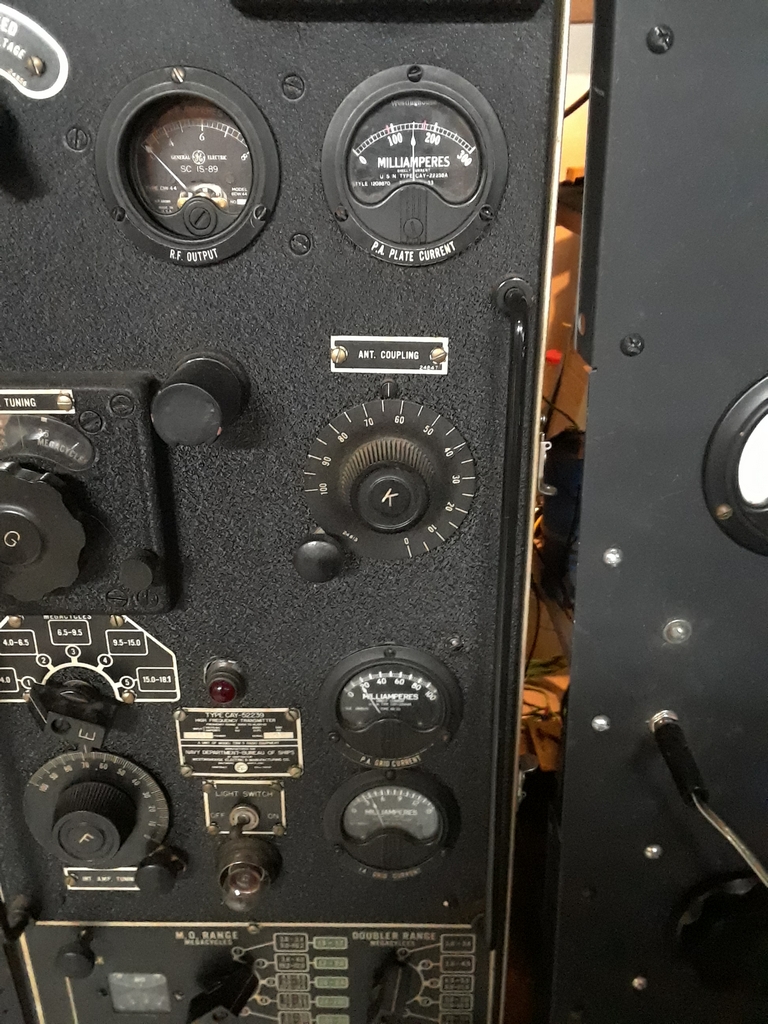
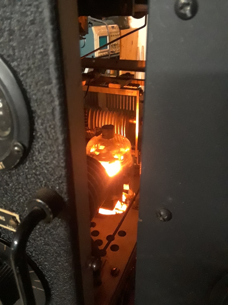
| The above left photo can be entitled "Beauty and the Beast" and I'll leave it at that. The right photo shows the 813 glowing and ready for action. The TBW comes with screened panels for the sides and rear, and for normal operating I have those in place not only for RFI considerations, but also for safety. |
What's next?
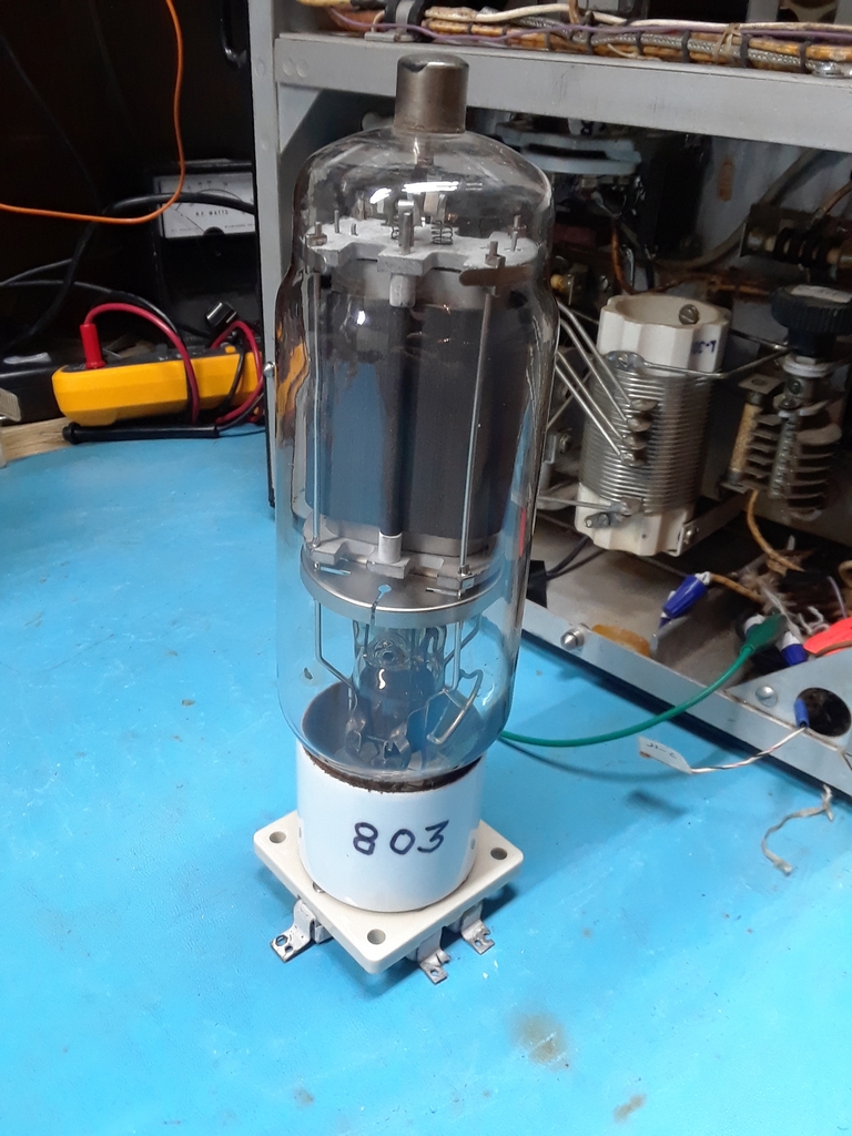
| I had planned to replace the 813 with an 803 and soon found out that the 803 socket required for the TBW is not the one you can get off the internet. It is physically smaller. Fortunately, a kind denizen of the "milsurplus" or "arc5" reflector had one and sent it to me. |
 -- --
|
|
I have decided to rebuild the power supply. As much as I think the rollable power supply is great, I desire a power supply that does not weigh 160 pounds. Another reason is that Bob told me there are grounding issues between the supplies and there is no ground connector on the 120VAC plug for ground loop concerns. These issues, as well as the weight, have made me decide to rebuild the power supply (using most of the same components). One supply will be for the 2KV, the second will be for the 500V and Bias supplies, and the third will be for the filament supplies.
As I was scoping out the 813 to 803 conversion I received an email from someone on the east cost informing me they have a stock TBW-4 and it's associated Rectifier Modulator Unit. Was I interested? Ha! Need you ask! To make a long story short, you can see the TBW-4 in the TBW-4 section of my web site. I don't need two TBWs, and will probably end up selling the TBW-5 once work is done on the TBW-4. Since the TBW-5 works, I may just sell it as is and include the 803 and socket if the new owner wants to convert it back. |
Classic Exchange (CX) October 2021
Listen here! TBW-5 on 40M CW!
Copyright (c) Mark S. Bell 2021