I used a B&W 5100B as a Johnny Novice in the early 1970's and used a second one between 1999 and 2017 as my main AM transmitter. The B model is an excellent radio for AM -- it has good audio quality and will produce around 90 Watts of carrier on 10M. I've many a fond memory of nice rag chews on 10M AM in the early 2000's as we came off the peak of the last solar cycle...
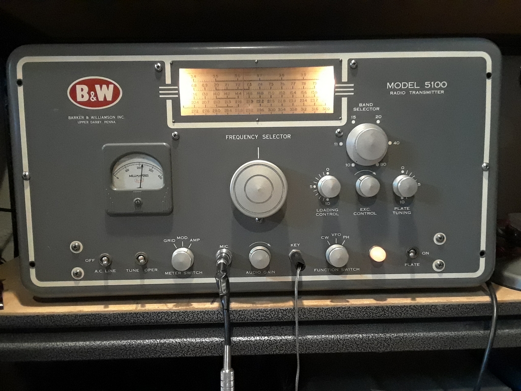
My fondness for the "B" made me want to pick up the 5100, the "B"s predecessor, that was produced between 1954 and 1956. I acquired my 5100 in Pittsburgh PA around 2005. It had issues, and it was used on and off over the years. Since I primarily do AM on 10M it wasn't an issue not having a plate modulated AM transmitter available after selling my unit at the bottom of cycle 24. With the coming of Cycle 25, I decided it was time to get it ready for some 10M AM fun. It is now my main AM transmitter and sits ready on 29.0 Mc.
One could purchase the separate 51SB SSB generator if desired. My unit, as obtained, was a 5100S variant as it had the internal “NORM/SSB” switch installed on the rear of the RF Multiplier unit with the cables for the 51SB. Earlier 5100 models did not have the switch and B&W provided a modification kit for this purpose. While I have an old QST advertisement for the "S" variant I don't know if all 5100s produced after a certain date were S variants, or one could purchase a “non S” or “S” variant throughout production.
Check out the "service notes" link below for details on how 5100 owners could convert their 5100 for use on SSB.
Initial checkout.....


During this time I performed preliminary testing of the radio. AM worked but was anemic, CW operation was erratic. The SSB/AM switch needed to be completely disassembled, cleaned, and restored along with the associated wiring. I figured if I was going to do that, I might as well disassemble the entire RF Multiplier stage for cleaning and restoration. Since I wanted to get the radio on the air as soon as possible, I used an RF Multiplier stage from a hanger queen 5100 I had purchased.
Capacitor C36 (screen grid current adjustment by the front panel "Exciter" control) had been damaged when the hanger queen 5100 was shipped to me. The control was pushed back causing the rotors and stators to touch. I used a small screwdriver to bend them apart, and tried initial tune up. This didn't work too well. Ip and Ig were very high, and I didn't catch it fast enough and managed to zorch screen resistor R25 or R26.
I proceeded to remove C36 in hopes of further repair. While "fixing" the cap, I cracked the ceramic casing. I figured some JB Weld would fix the cap, but I wasn't confident I could do anything to help the rotor and stator issue. My buddy Dean K5DH provided me with a replacement for C36. The replacement was 36 pF instead of the required 28 pF, but I figured that aside from being more touchy on tune up, it should work just fine. Besides, it was free and fit the mounting holes.....
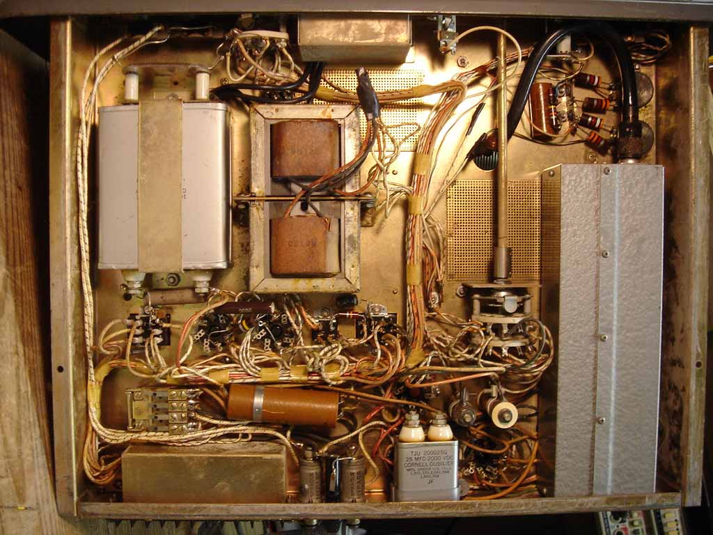
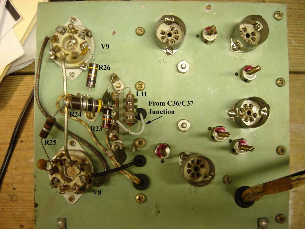
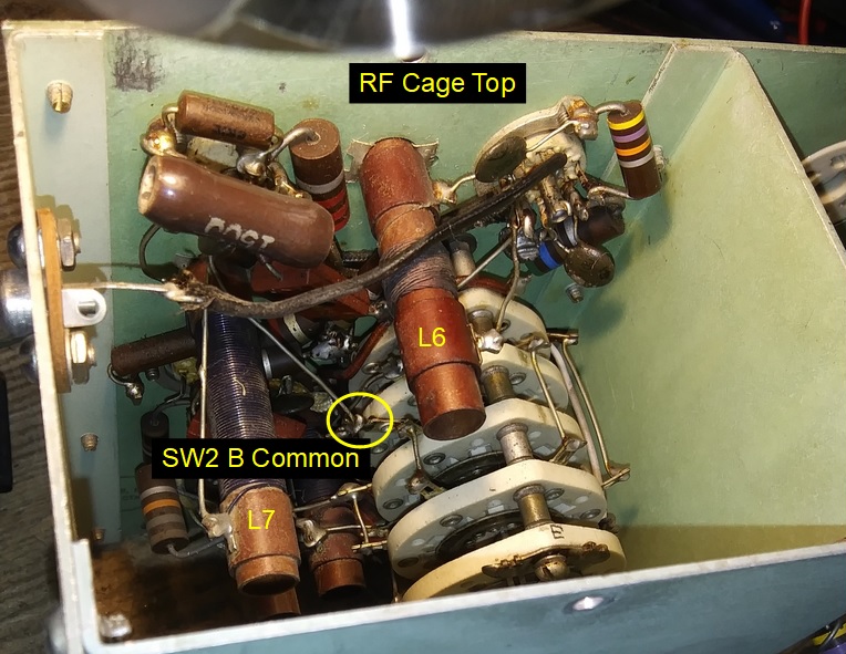
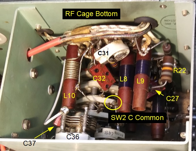
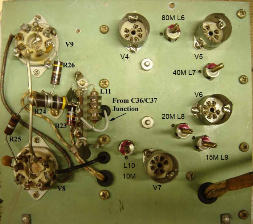
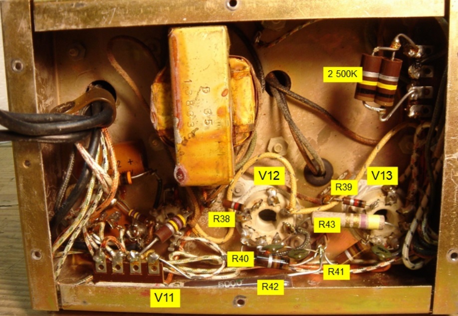
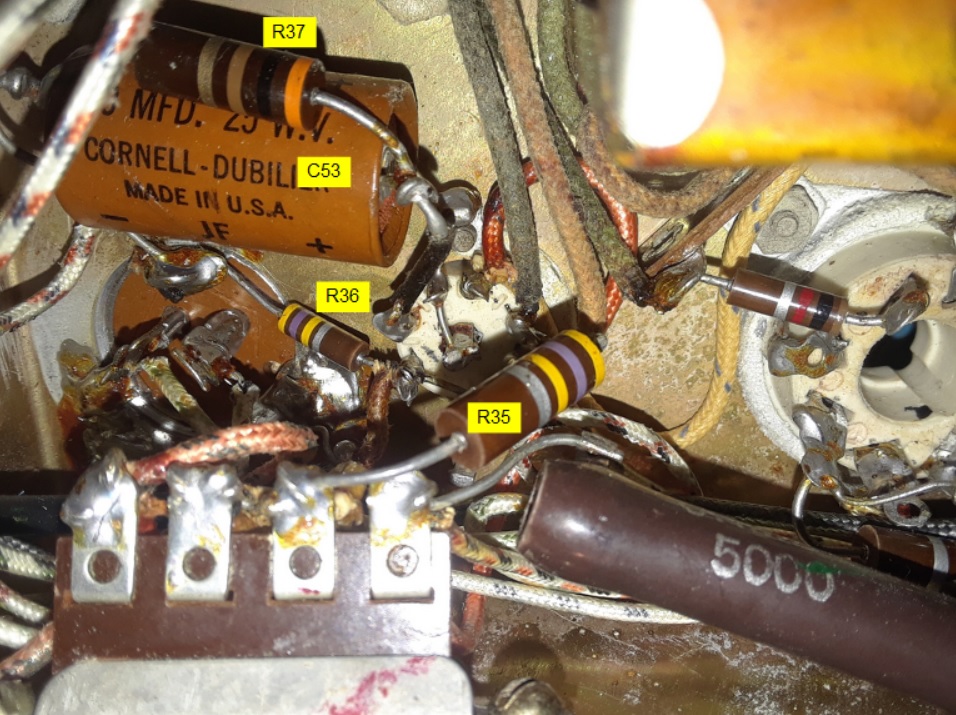
Here are some annotated pictures of the repaired RF Multiplier unit.
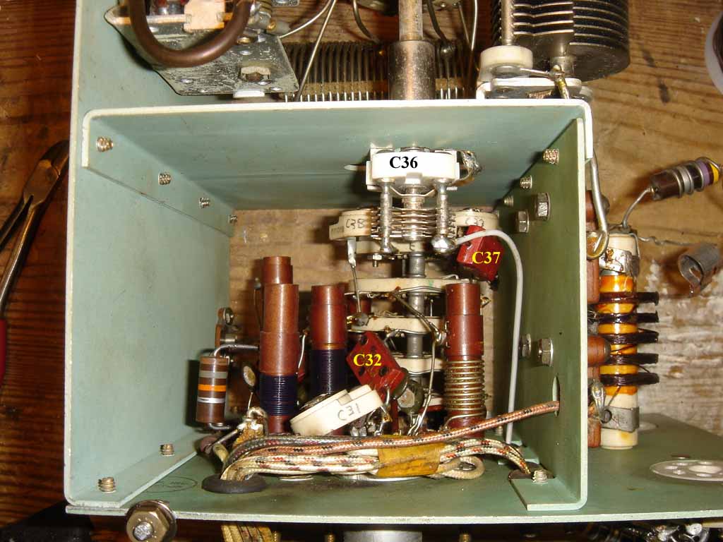
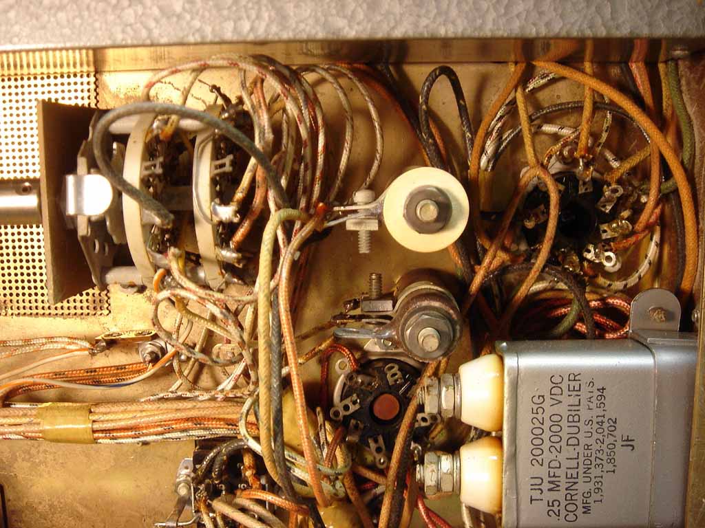
Switch SW 2 runs through the RF Multiplier unit. Here are some photos showing the location of the common tab of each switch wafer.

Initial 5100 transmitter had a multi-tap resistor (R49) to provide various voltages and this is typically shown in the schemaitcs:
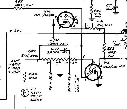
At some point in the 5100 production run B&W provided instructions to replace R49 with two potentiometers, one to adjust the modulator resting current and one to adjust the PA resting current. These pots are near the 6146 finals. I do not know if B&W changed their production run for this, but I've never seen a B&W schematic that has the R49 change.
Note that in the schematic above, R55 and wiring from R49 lug 6 are deleted when this modification is made:
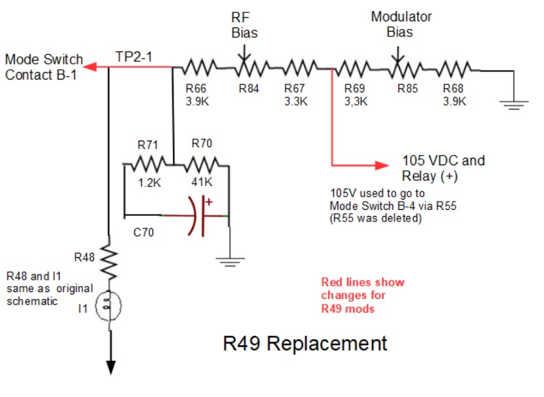
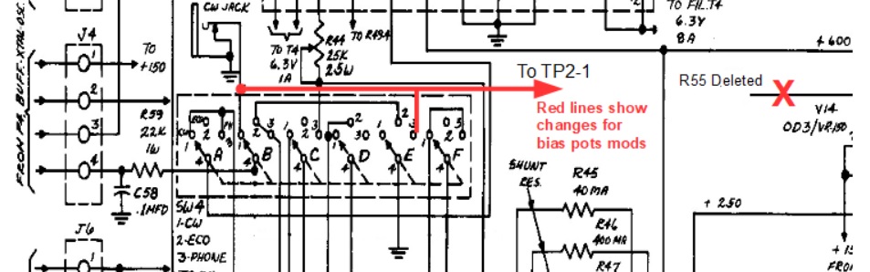
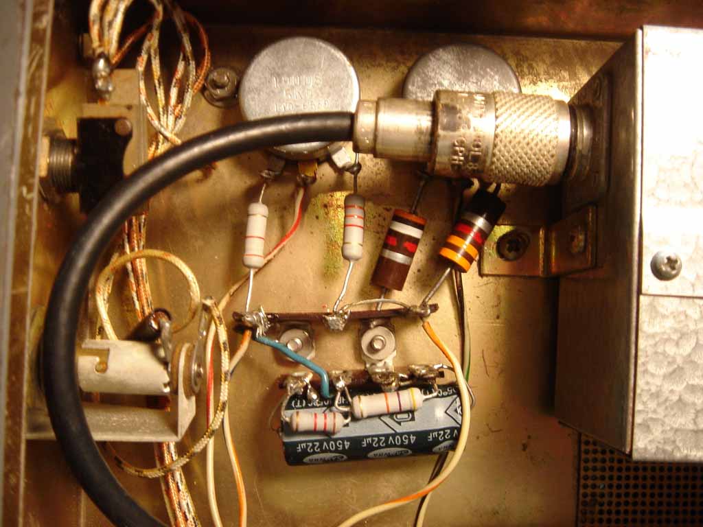
I replaced the RF Amp bias pot and associated resistors. The 450V cap is overkill, but it was on hand.
Meter Shunt Resistors.
Here's a picture of the meter shunt resistors on the Meter Selector switch.
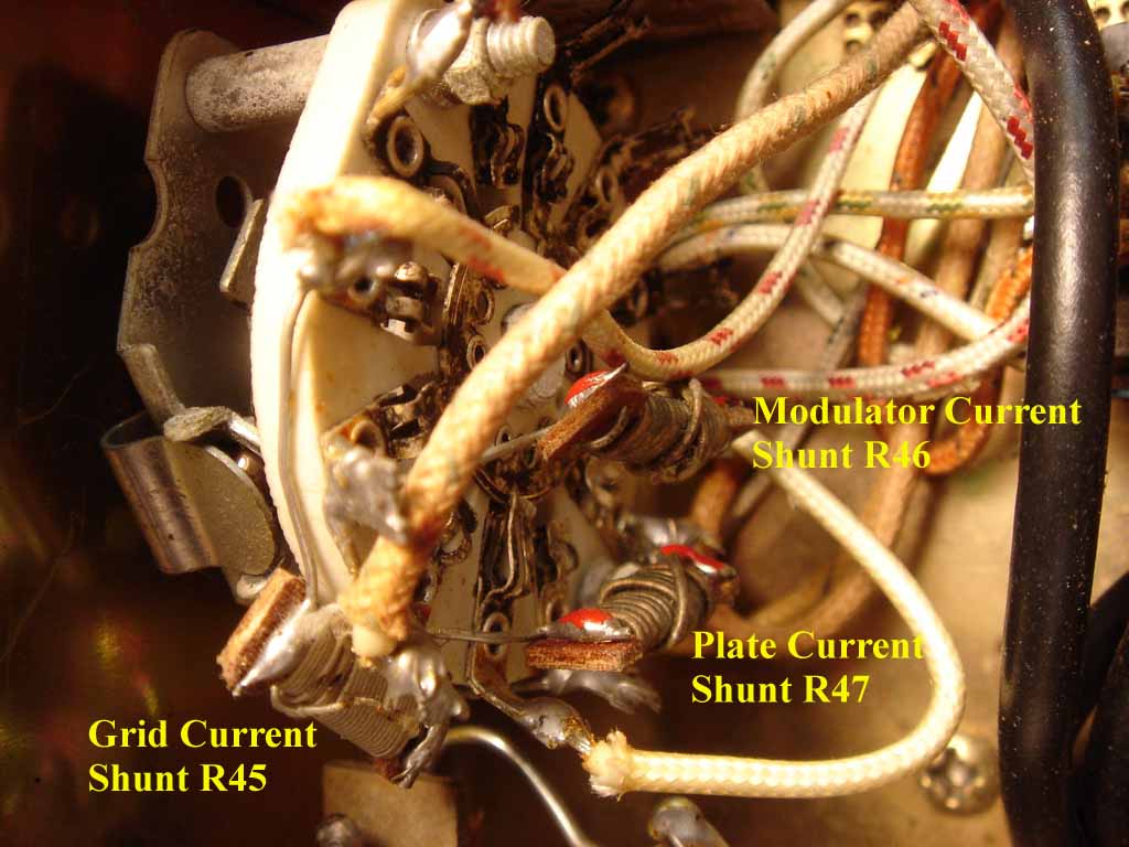
The schematics do not mention the values for these resistors, only that the grid resistor provides full scale meter deflection at 40 mA, and the other two provide full scale deflection at 400 mA.
I measured the grid current shunt resistor to be 5.2 ohms (both on my DVM and VTVM).
I tried to measure the other 2 shunt resistors, which should be 1/10 of the grid shunt resistor (0.52 ohms) as they both want full meter deflection at 400 mA. My DVM gave me a reading of 0.7 ohms, and my Heathkit VTVM was around 0.3 ohms, so not a good correlation there.
However, the VTVM and DVM did give me the same value for the grid position, that being 5.2 ohms. So, one can infer that if 5.2 ohms is supposed to give full deflection at 40 mA, then the correct value for the other 2 shunt resistors should be 0.52 ohms to give full scale deflection at 400 mA.
Jim W5JO sent me the following: "I just dug out the old switch with the shunts attached that I replaced in my 5100. My Triplett and digital meter said 7.5 and .7 ohms. Neither can read below on ohm to more than one place"
So, what are the correct values for these shunts? Good question; we have some data points. When I start indepth work on the 5100, I'll gin up a test circuit and see what provides the correct meter deflection.
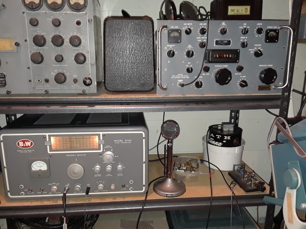
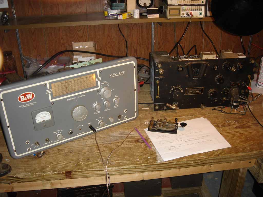
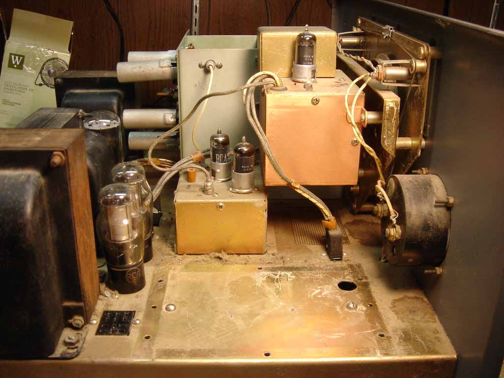
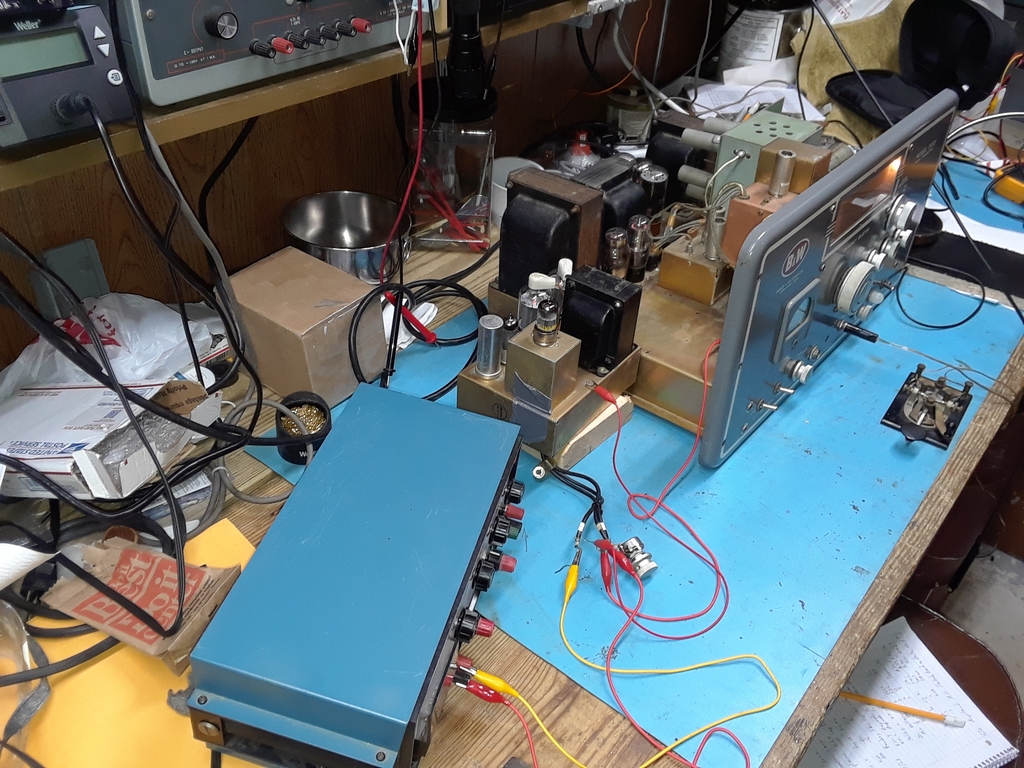
Made several contacts on 10M AM as well as one on 15M AM over the past several weeks. Here's the 5100 paired up with my Hallicrafters SX-101A:
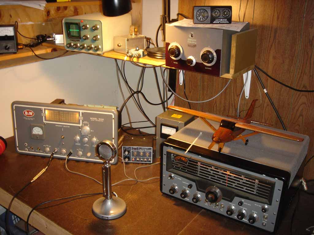
Power output is a bit low on 10M, but I didn't align it before initial testing. I wanted to basically make sure that the radio played before I spent the time on a more in depth restoration. Audio reports have been good... but.... there's always a but.... two folks said my audio sounded like it was going into "oscillation"; this was accompanied by a very slight crackling from the modulator stage. The first time this happened it went away and the audio returned to normal. I made several contacts afterwards with no one reporting any problems. The last contact I again heard the crackling, and the audio remained degraded. I experimented by turning down the audio gain (barely enough to modulate) and was told the audio still sounded bad.
So; time for detailed work to begin. This will start with a thorough check of the modulator stage and upgrading the audio as per the mods provide me by Moe W5KD some years ago.
The 5100 paired up with a BC-342-N for the Fall Classic Exchange on 80 and 20 CW. The modulator subchassis has been removed.
Well, 14 years have gone by and the blasted modulator subchassis is still removed and parked on the shelf where I put it... 14 years ago.... Time to get this beastie ready for 10M AM!
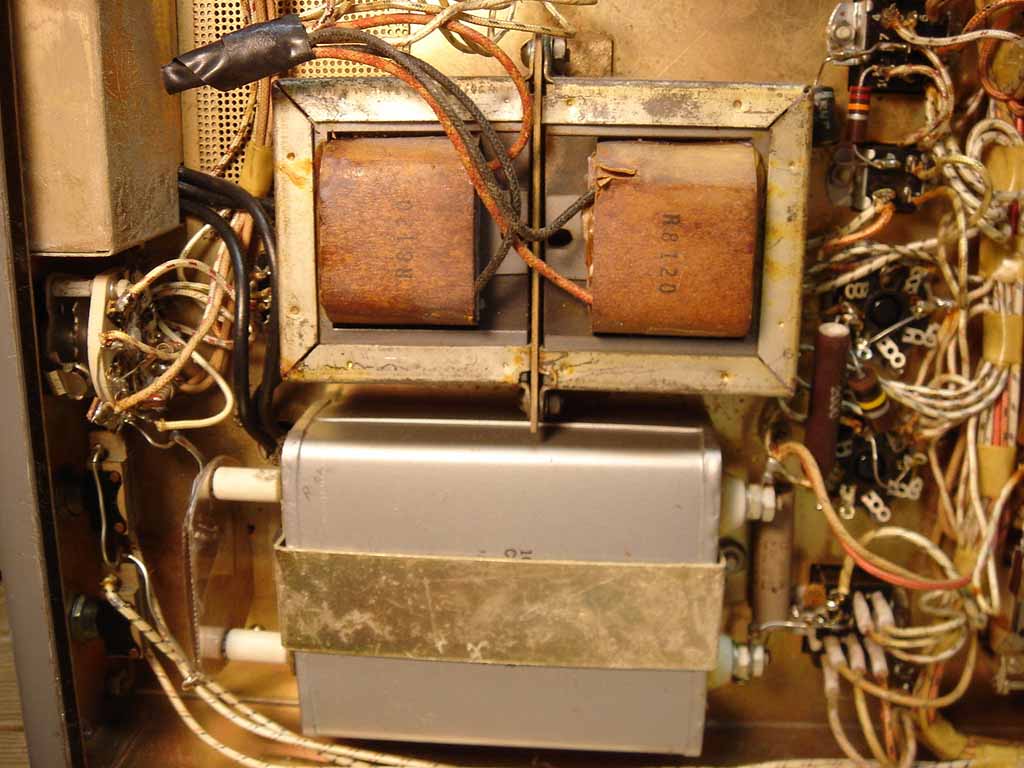
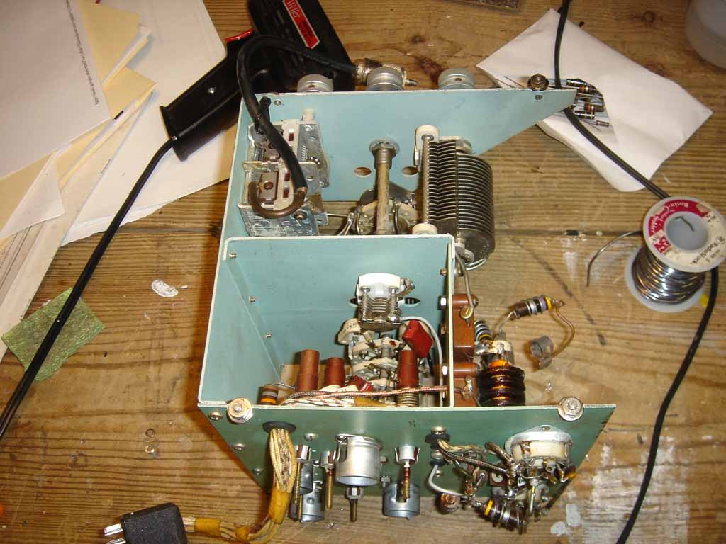
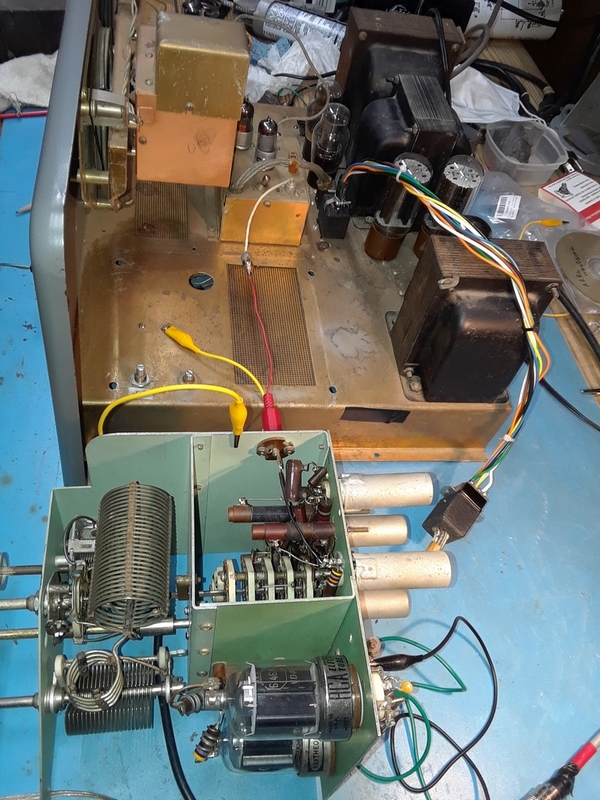
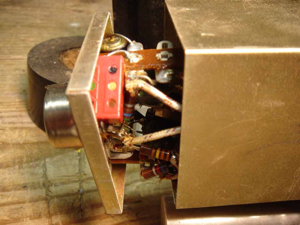
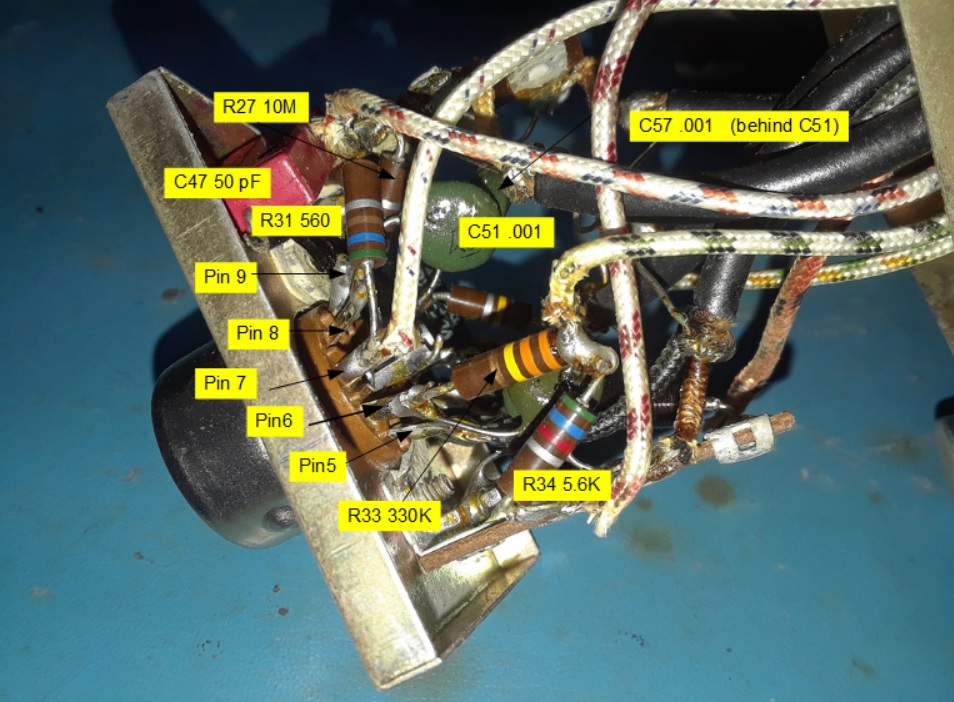
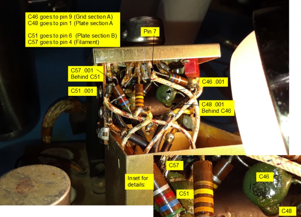
First up was to align the RF multiplier unit and replace a few components on the back of the unit:
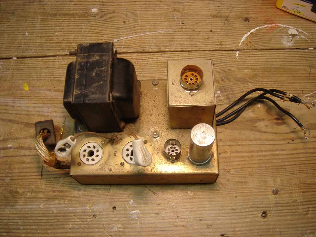
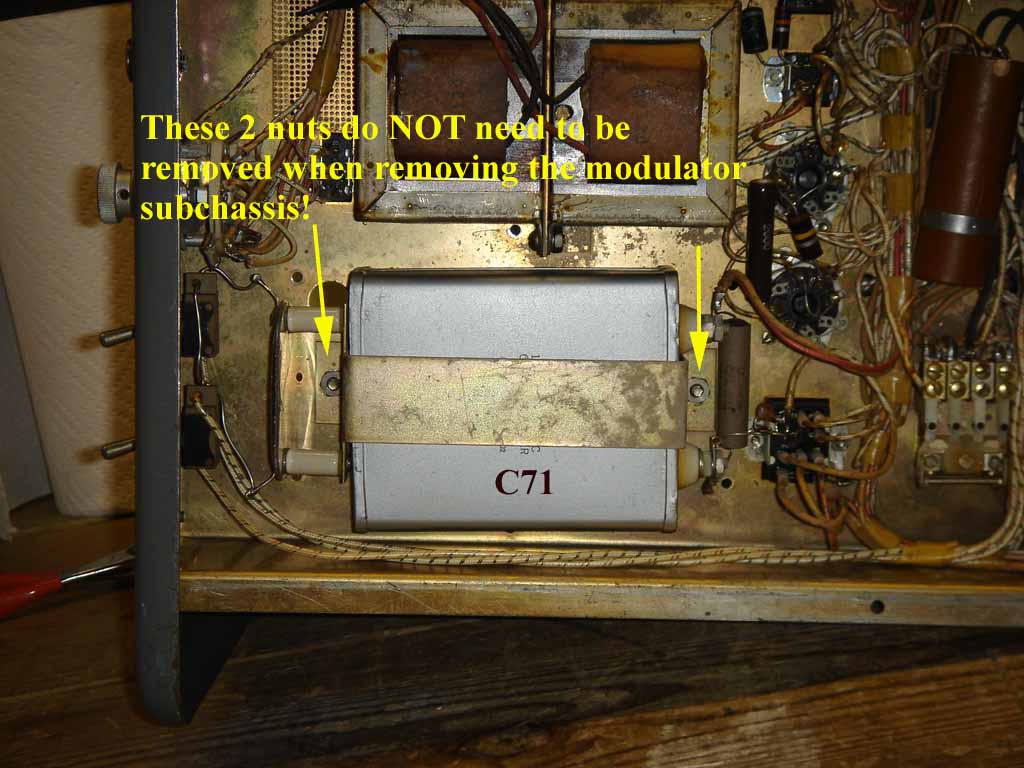
The modulator subchassis:
The modulator subchassis is secured by 6 screws under the main chassis. You do NOT have to remove the 2 nuts securing C71 as indicated in the following photo. The screws that secure those 2 nuts are accessible from the top of the main chassis (that is covered by the modulator subchassis.....).
Unlike the 5100B which connects the mic and audio pot control to the subchassis via plugs, you have to unsolder all these connections on the 5100 and feed them through a hole in the main chassis when removing the modulator subchassis.

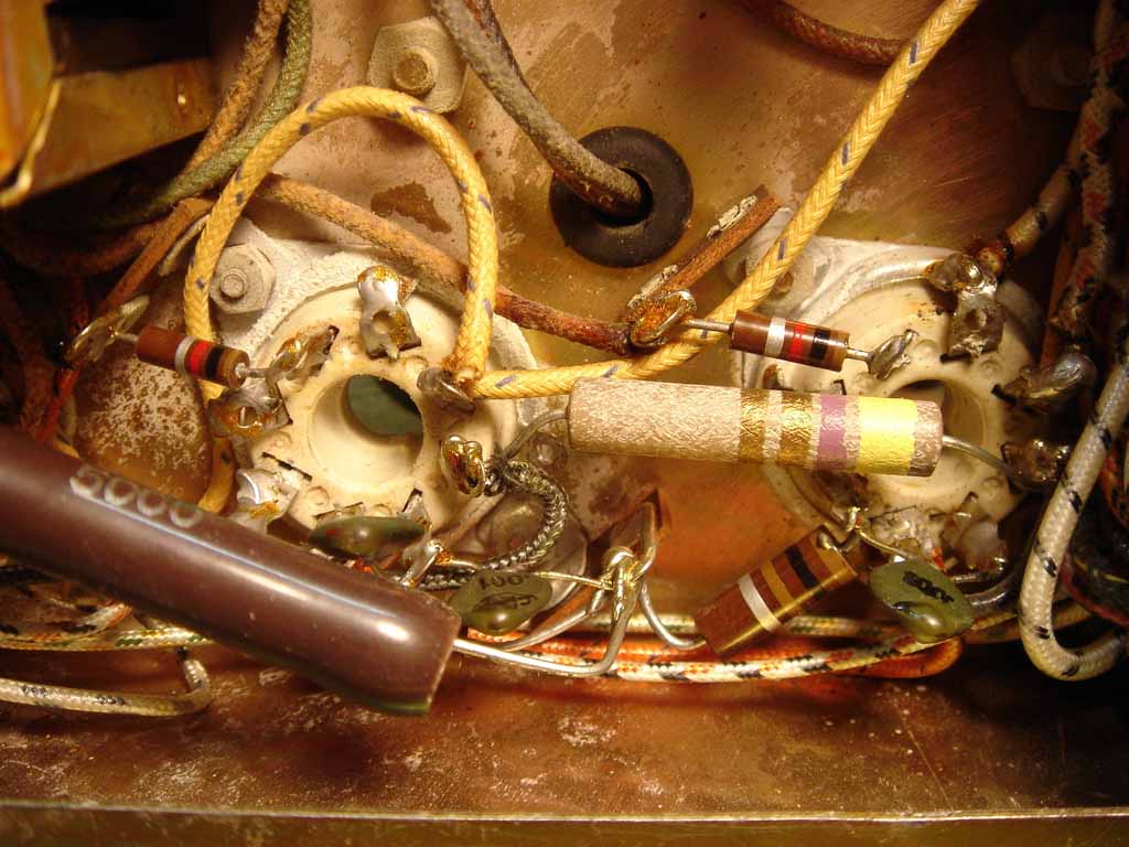
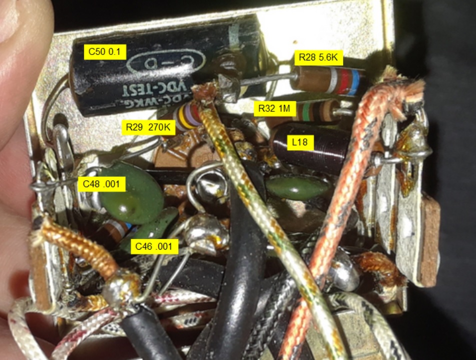
These are photos of the 6U8 socket atop the "Missile Tower". Aside from out of tolerance resistors, C50 should be replaced.
Testing of the modulator with my Heathkit Audio Generator:
Ready to go with the R-390A on 10M AM!