|


|
|
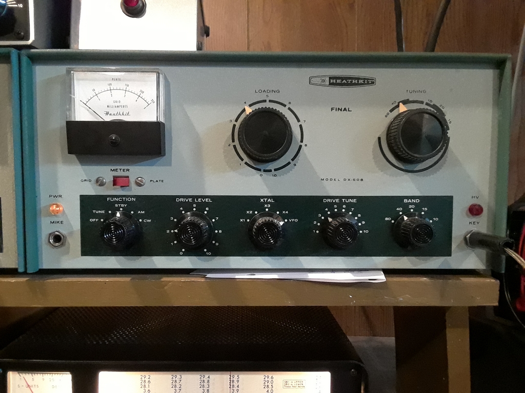
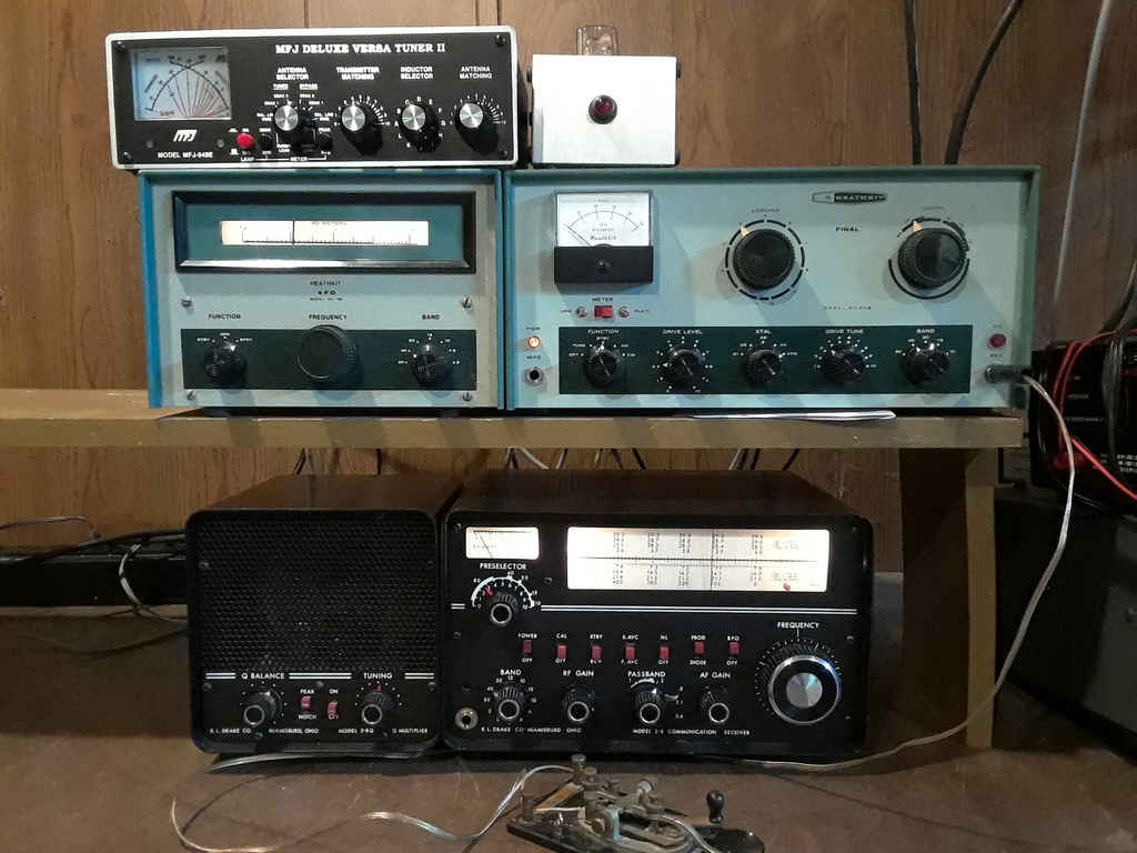
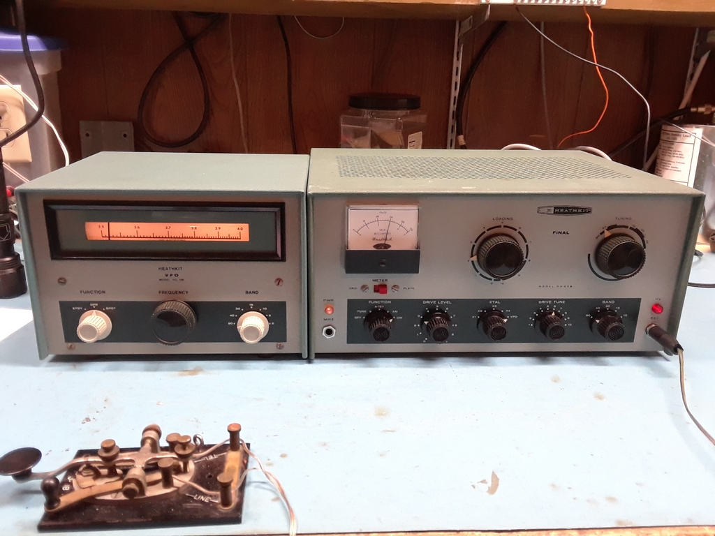
I received the DX-60B around 2021 from Ken N3CU. This transmitter, along with an HR-10B receiver and home-brew (HB) VFO, were Ken's novice radios in 1972. After sitting in his attic unused for decades, he didn't want them to deteriorate and wanted them to go to a good home. Here's the radio as received:
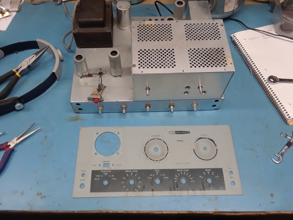
I was more than a little concerned about taking someone's Novice radios for obvious reasons, but after several conversations Ken said he was sure he wanted to give them to me. Thanks Ken! Ken recalled the DX-60B worked, but initial inspection showed there were issues with the transmitter. Numerous cut wires, unsoldered (or broken) connections, and new wires awaited under the chassis. We suspected some of the modifications were to enable the HB VFO, built by one of Ken's friends, to work with the transmitter. The front panel had a few cosmetic issues, the biggest of which was baked on tape residue between the Tune and Load controls. It took a lot of time and patience to get that tape residue off without damaging the front panel, and it turned out nicely!
|
|
Here's the home-brew VFO built by Tom Howey K1TWH! Yeah, it's a true Frankenstein, a creation only Boris Karloff could love..... but C'mon, how can you not love that big [National ?] dial and Johhson knob! And it even sports vintage 1970's Dymo labels!
Remember it was built by two 19 year old hams back in 'the day'...... and it worked well for Ken for several years! To say 'Good job' would be an understatement!
|
|
Since I have an HG-10B I didn't plan on using the HB VFO and it sits untouched. The tube compliment is an OA2, 6AU6, and 6U8. The 6AU6 is probably the oscillator and the 6U8 a buffer stage. Ken said the VFO derived power from the DX-60B, so I'm not sure what the filter choke is for.
I originally thought the VFO wasn't worth restoring but I've decided to transplant it into a bigger metal enclosure.
|
|
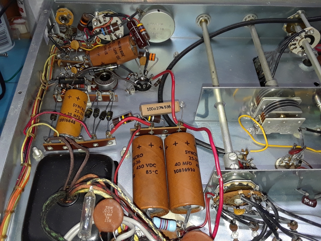
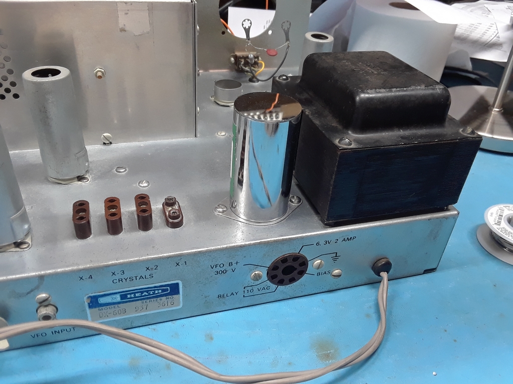
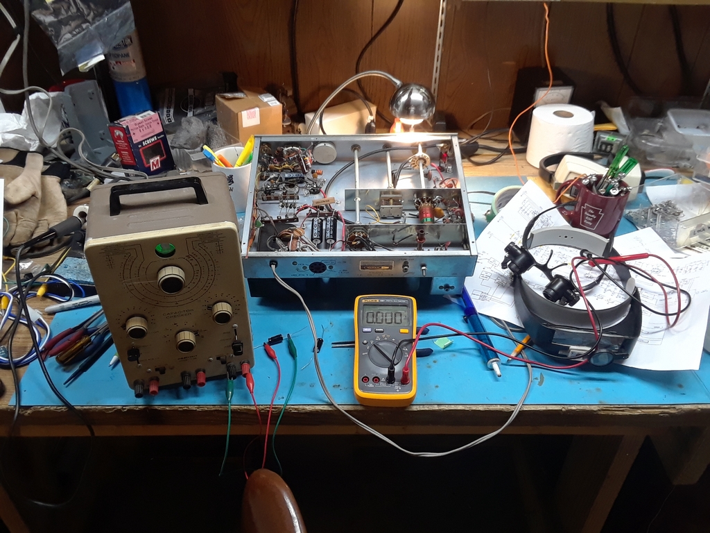
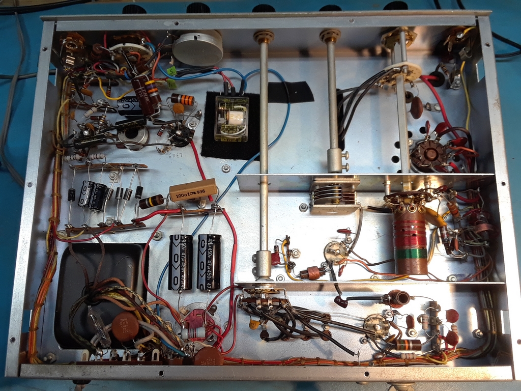
I decided to return the transmitter to stock configuration so began the process of removing non standard wiring, repairing solder connections and general repair/clean up.
|
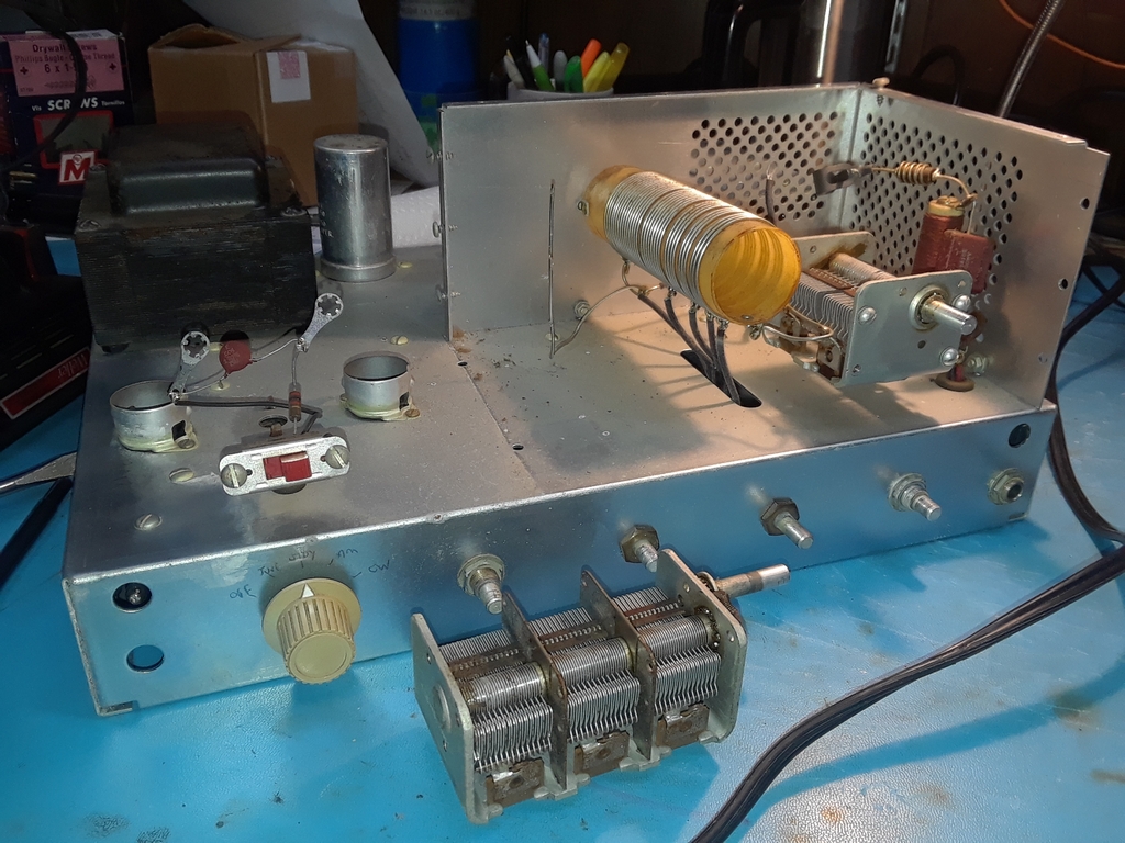
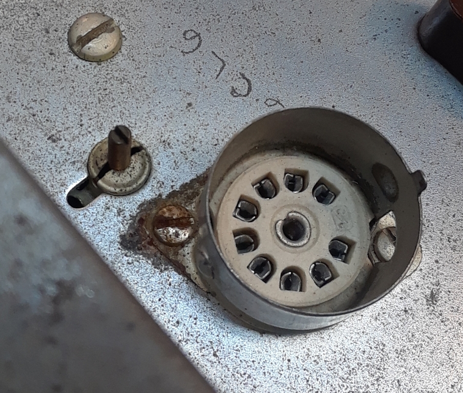
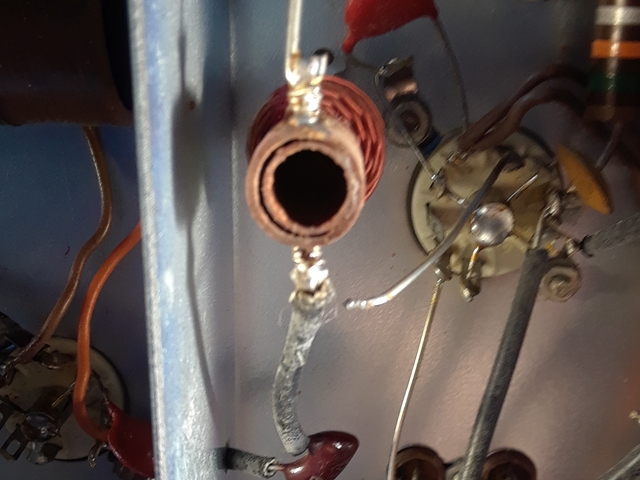
In the above photo, I suspect repeated cycles of heating (expansion) and cooling (contraction) caused this wire to break.
|
|
|
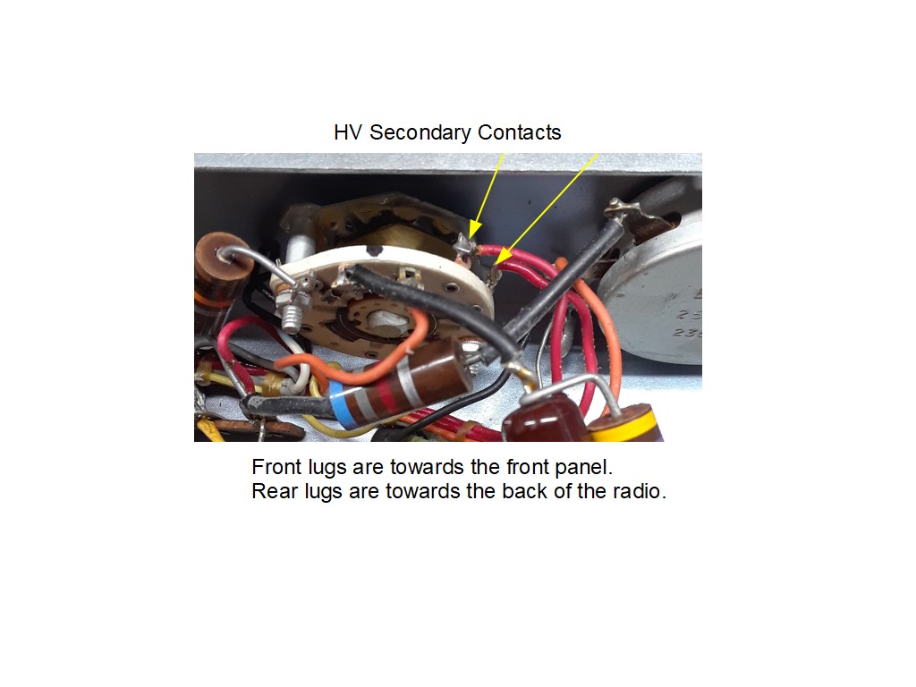
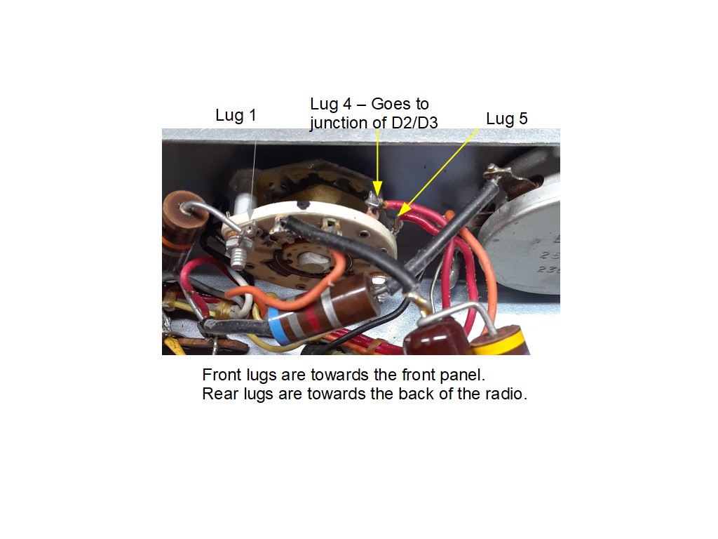
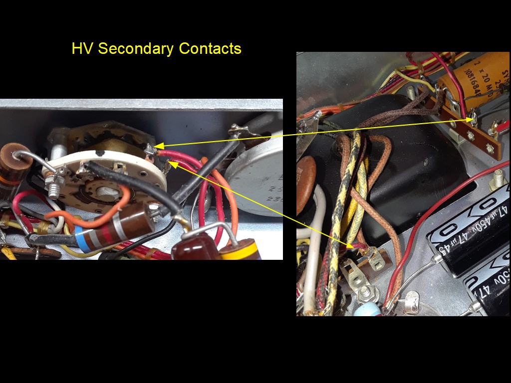
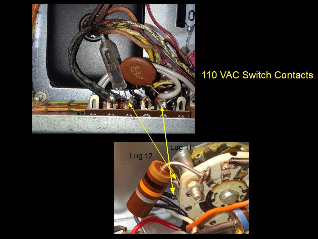
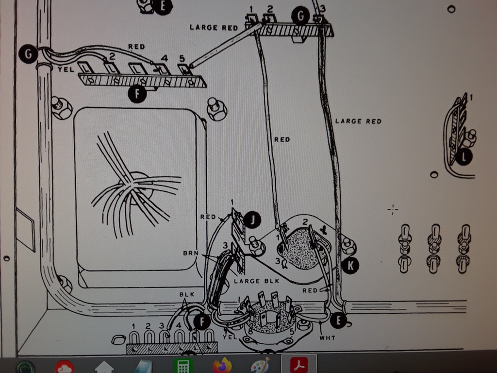
The other big issue was to address the power switch. This switch is a known failure point on the DX-60B and replacement switches are getting to be 'unobtainium'. For power ON/OFF, I elected to just leave the switch in STBY and control power via an external power strip. For 260 VAC secondary switching, I added a new 117 VAC relay under the chassis. Now the Function Switch contacts switch 117 VAC and not 260 VAC.
The well known modification is by VE6KQ.
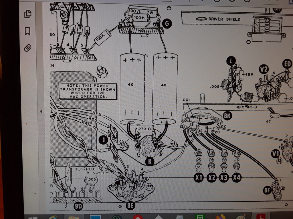
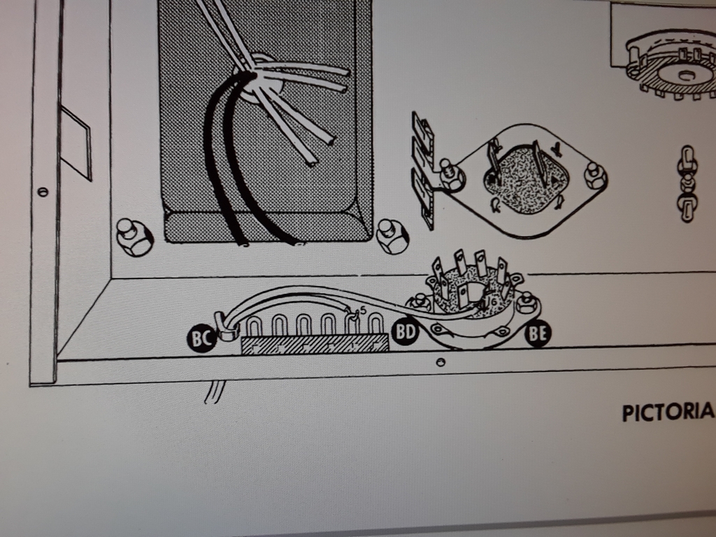
|
Smoke Test time!
Power output with 150 mA Ip and 2.5 mA Ig is as follows:
September 30, 2023 -- Getting ready for the Fall Classic Exchange (CX) ! 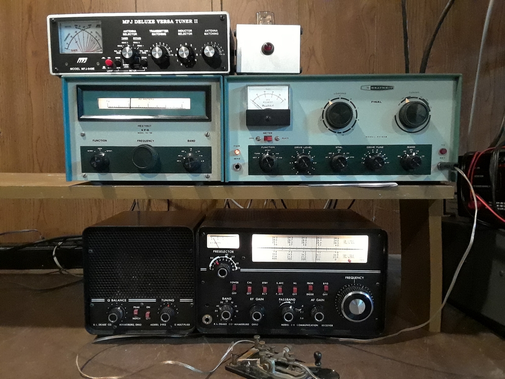
|
Copyright (c) Mark S. Bell 2024