
I clearly remember that summer day back in 1973 when at age 15 I rode my 3 speed Stingray bike to Perrysville Elementary School, where Milt was the principal, to take my Novice Exam!!


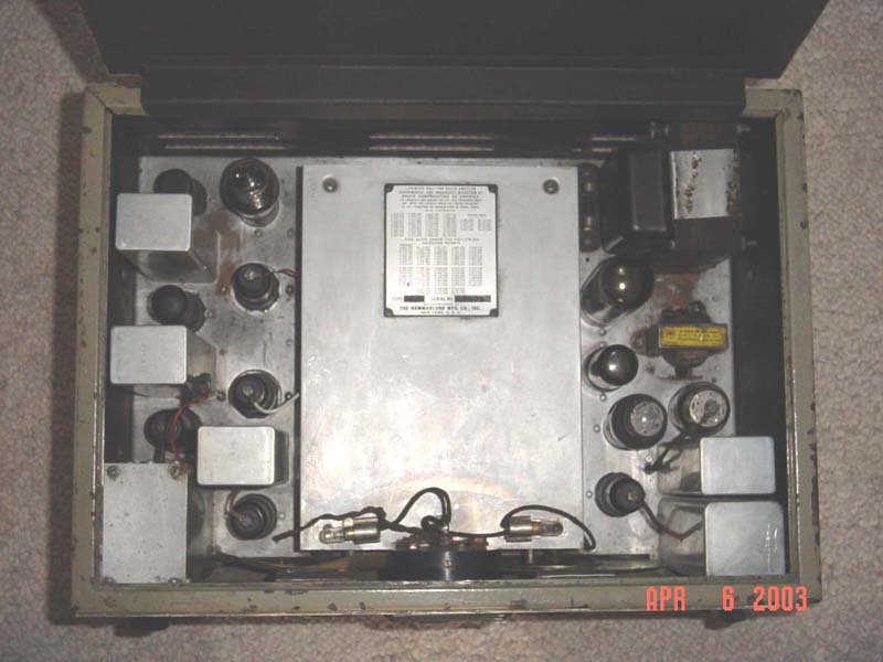
Restoration started.
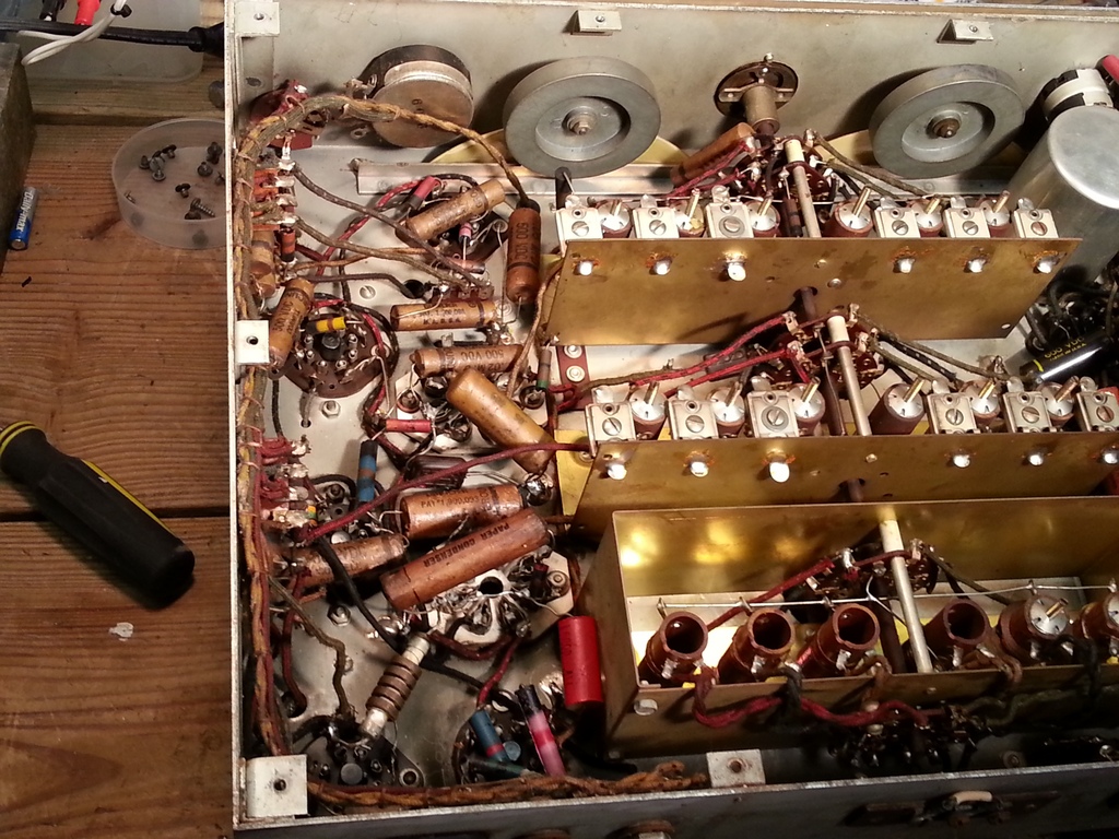
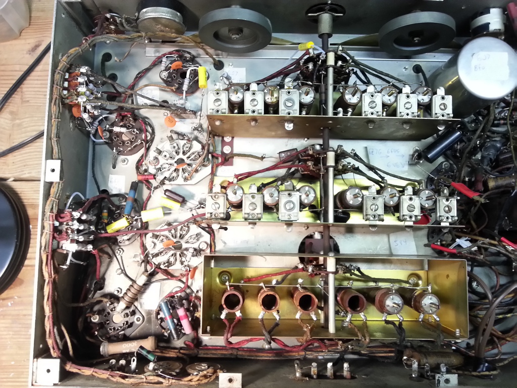
Half of the chassis underside has the components replaced. Here's some before and after pictures. I trued to reuse as many of the resistors as I could but not many were within tolerance.

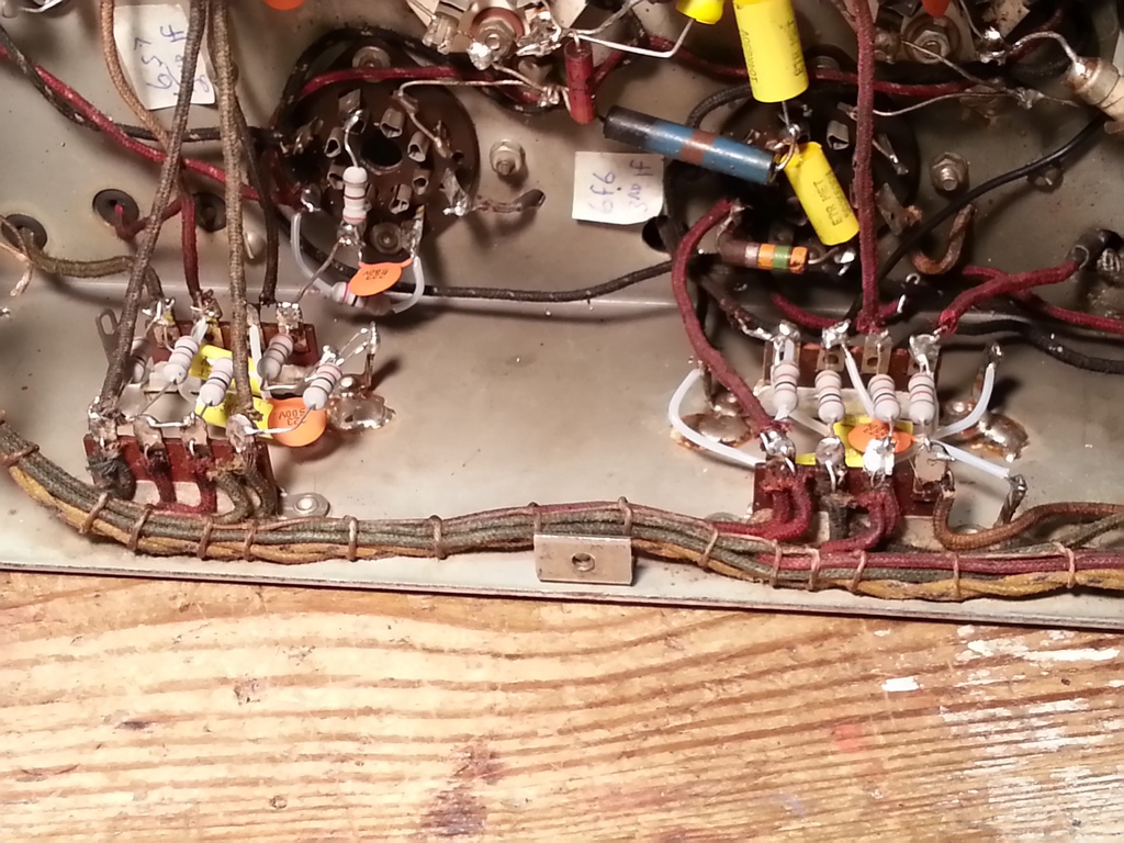
Some of the chassis holes that wires pass through have grommets and some do not. Some of those wires are pulled tight against the holes, and the insulation is 75 years old! I unsoldered those wires and slipped some heat shrink around the portion that passed through the chassis holes. It can be a tight fit, and in some cases I had to use a dental pick to gently persuade the heat shrink to go into the hole!
Here's the before and after pictures of the components in the RF Cage.
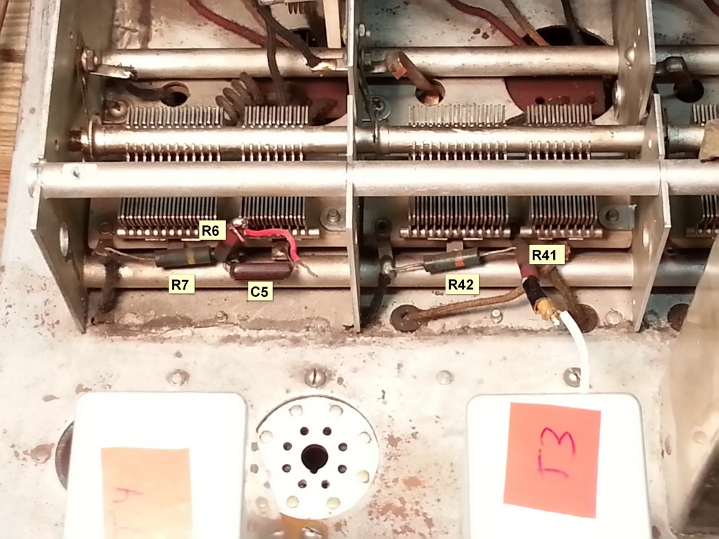

Surprisingly R7 (500K) was completely open. Note there are two wires (with that 75 year old insulation) that go through chassis holes with no grommets. I replaced those wires and routed them so that they do not have tension against the hole sides.
While inside the RF cage I reflowed all the solder connections.
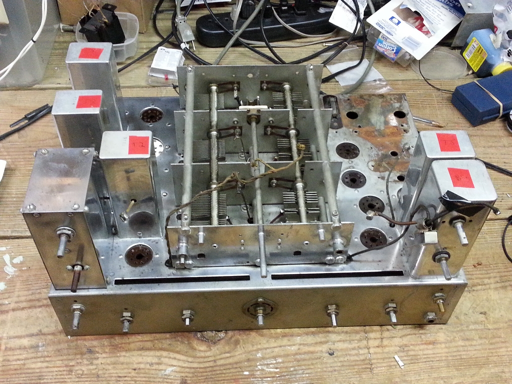
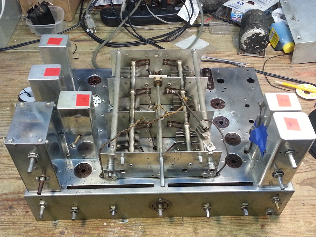
The other side of the chassis!

Here's how the right side of underneath the chassis looks. The power transformer and chokes have all been removed, as well as the audio bypass cap and 3 stage filtering cap.
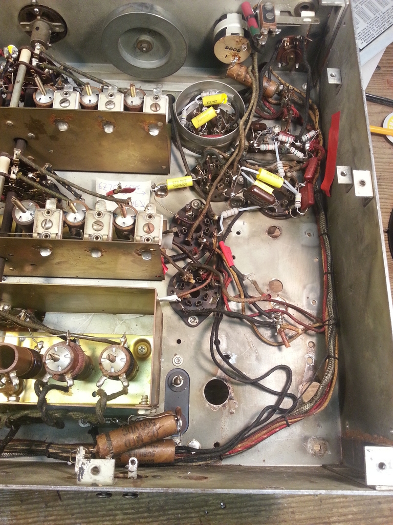
I need to replace the 3 remaining paper caps, and I'll do that when I run the new (3 conductor) line cord.
I'm trying to convince myself that the ON/OFF part of the AF Gain switch is OK. If I gently pull on the back I get about 30 ohms resistance at times when the switch is ON, so I'll have to keep that in mind.
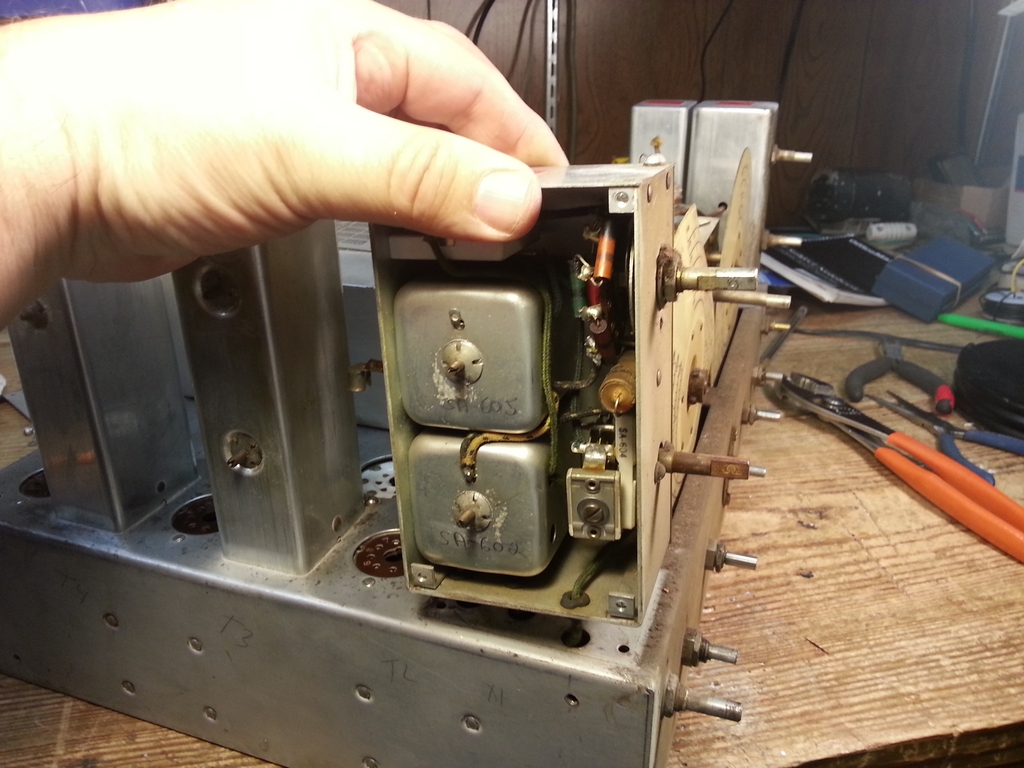
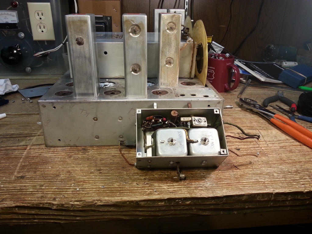
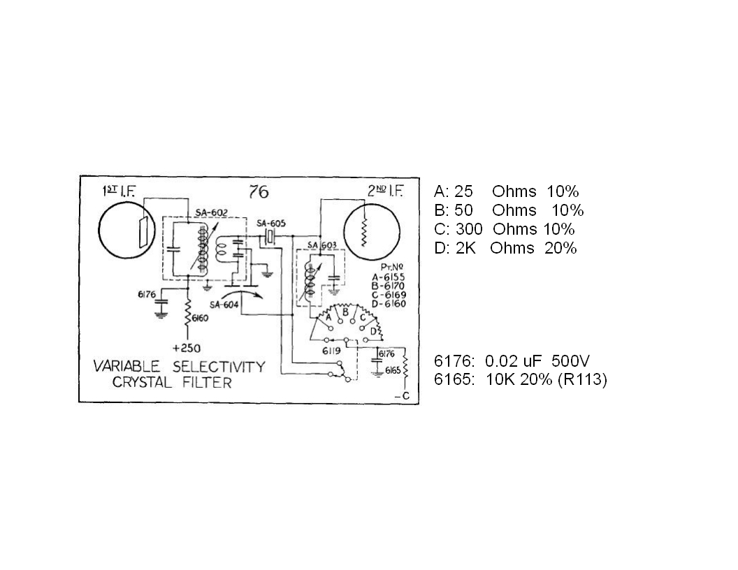
The next item I worked on was the Crystal Filter. As the following photo shows, you can access the inside of the filter by removal of a side plate, but you can not get to R113 and access to the one end of the 0.02 uF capacitor is not easy. It is best to just remove the assembly from the chassis, which fortunately is pretty easy.
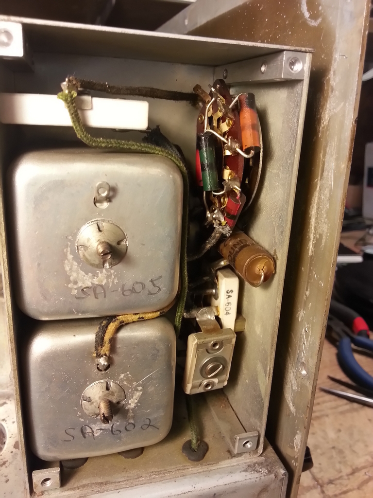
First remove the front panel. All the controls are secured to the chassis by nuts under the front panel and are not effected by the removal of the panel itself.
Next, unsolder the three wires under the chassis coming from the Crystal Filter. Finally, gently remove the filter and remove the top and side panels.
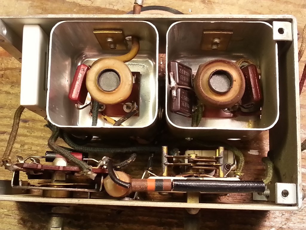
Here's a close up of the "innards" of the Crystal Filter. The resistor at the bottom of the photo is R113. The large white rectangle at the left (really the top of the filter) is Y101, the 455 Kc crystal.
Here is a more detailed photo of the parts placement in the Crystal Filter subassembly, along with an annotated version of Figure 2 from the Hammarlund manual:
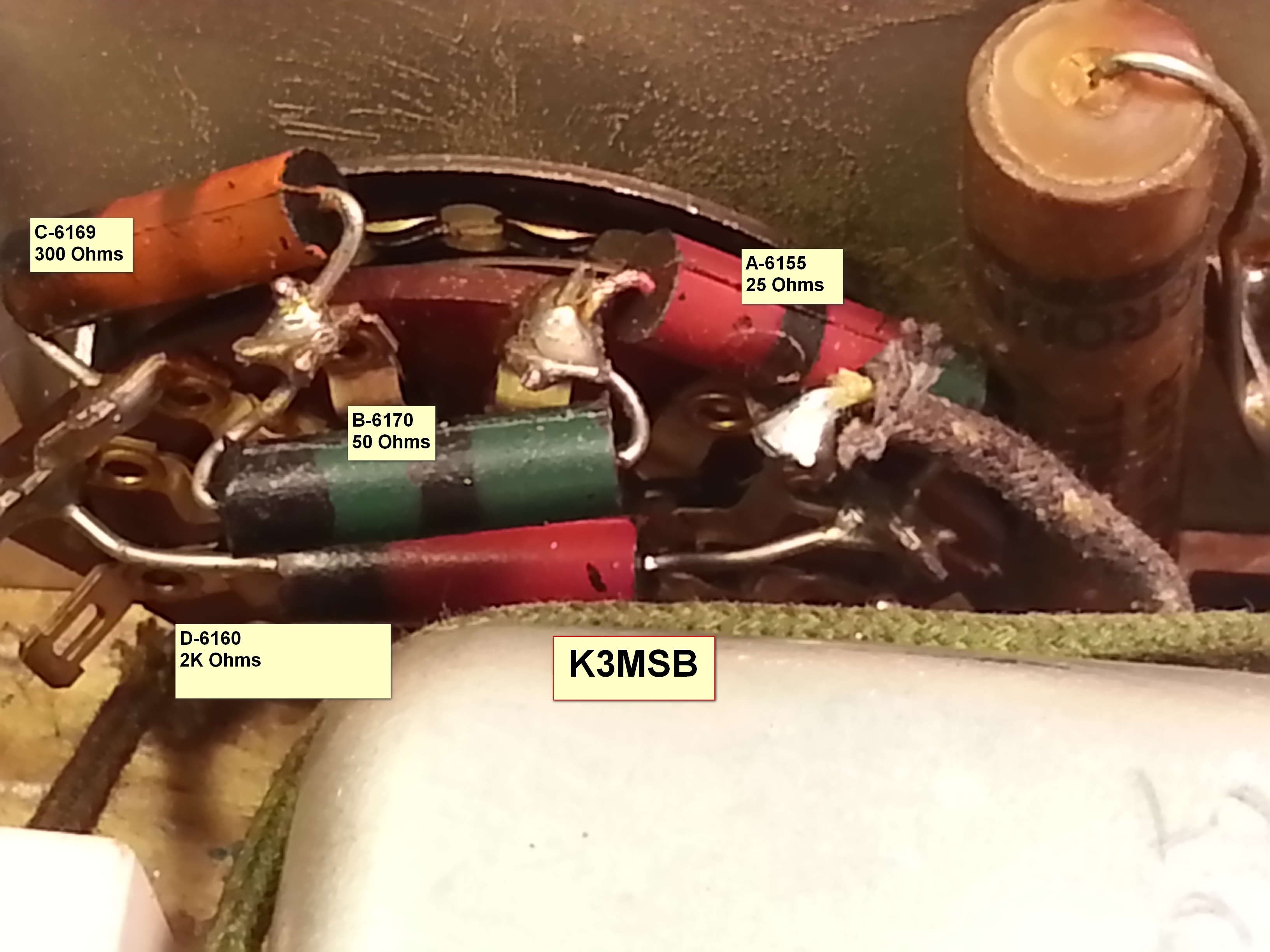
I think three of the five resistors needed replaced, and of course the cap was replaced. When done, clean everything, put the top and side panels on, and remount on the chassis!
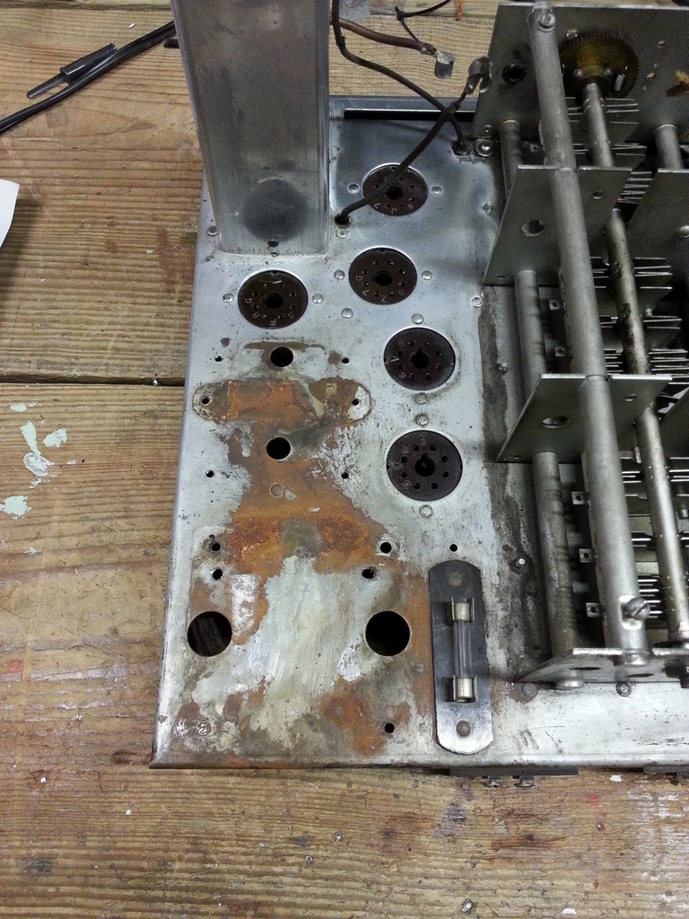
While the Crystal Filter was fun to work on, the next item wasn't. That was the big rust area on the chassis under the power transformer. Typically for rust that's not bad, I use Naval Jelly followed by a good cleaning with water, followed by a polishing with Never Dull. Afterwards, I apply a nice coat of Turtle Wax. I've used this method for years and it's provided me with a nice looking chassis and no return of rust.
For this area, it took more than a few applications of Naval Jelly. The top surface of the chassis was gone and the chassis discolored. While this was the condition of small areas on the other side of the chassis, I decided to apply a coat of Rust-oleum Crystal Clear Enamel spray. It's good for up to 200F, and I doubt the chassis surface is going to get that hot. This was my first attempt to spray seal a chassis.
Here are photos of the original rusted area before and after application of Naval Jelly and Never Dull:

Now the radio is taped for spraying, and finally the end result:
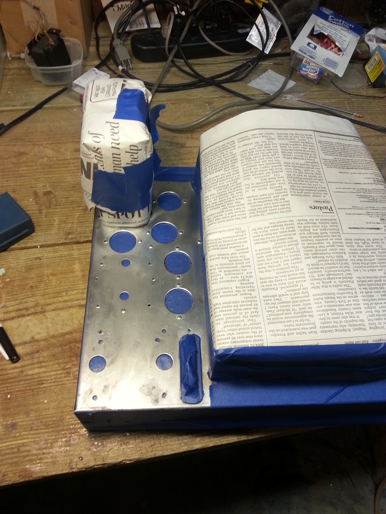
Yes, the chassis is discolored where the rust used to be, but there's nothing to be done about that.
Well! Getting close to smoke time! Just a few more odds and ends to reinstall, such as the new (original) power tranfromer, chokes, filter and audio caps, replace the dials.... Stay tuned!
It works! At long last, I drove the radio on the air a few days ago!
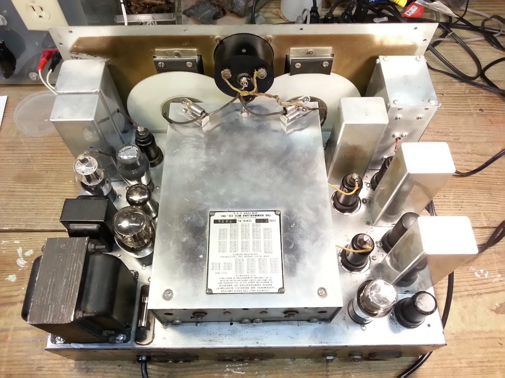
The first order of business, since the June 1st update, was to install the "new" audio and power transformers, as well as a three conductor power cable and associated safety capacitors. As the left image shows, I tried to save the original wire snippets that went to the two filter chokes and the filter capacitor. In the end, it was easier to just remove them and have those sockets basically cleaned and empty.

A big tip of the hat  to Dennis W7TFO who provided these transformers as well as the new dials for my radio!
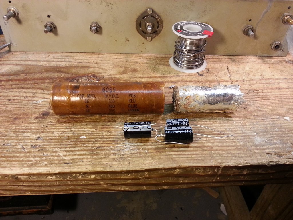
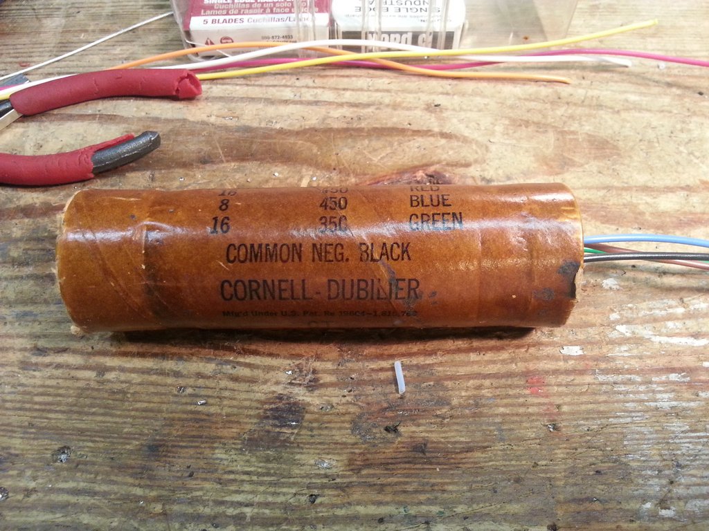
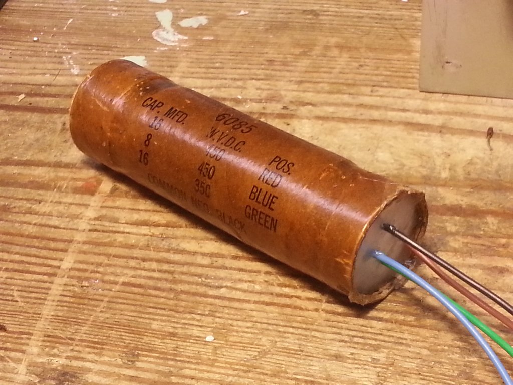
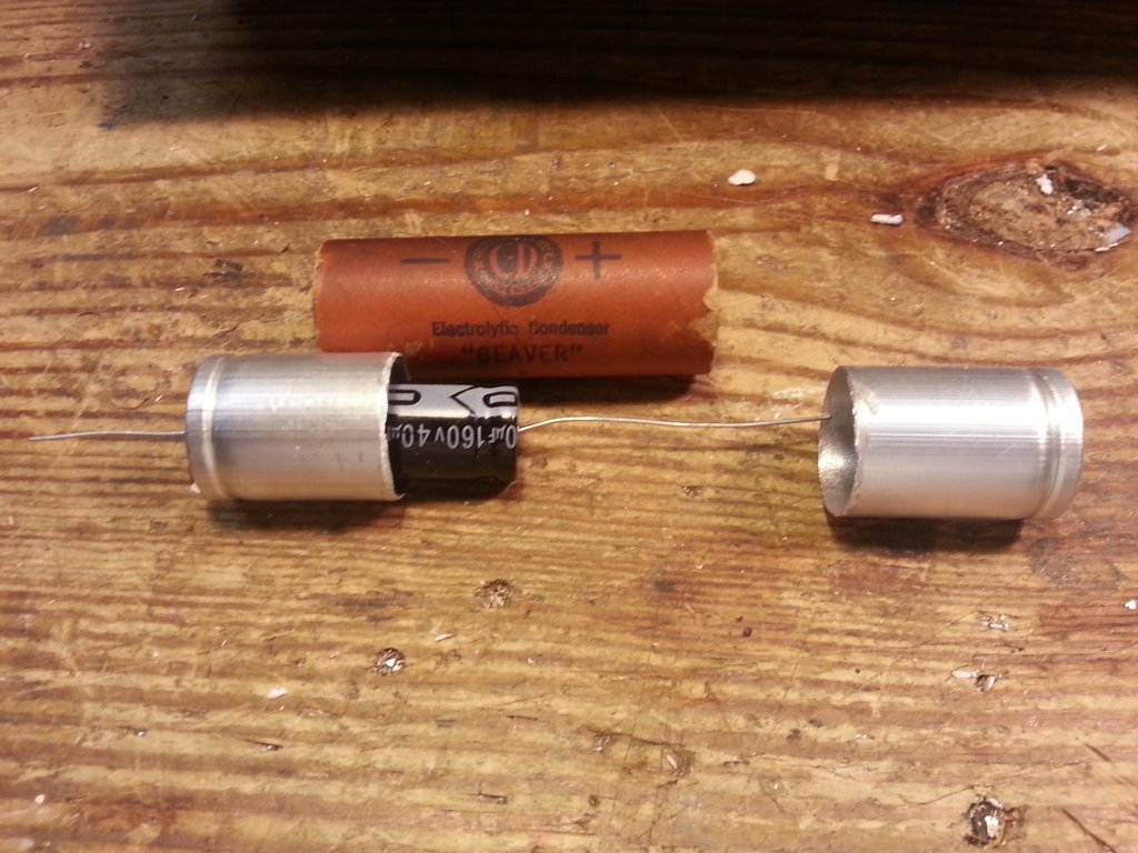
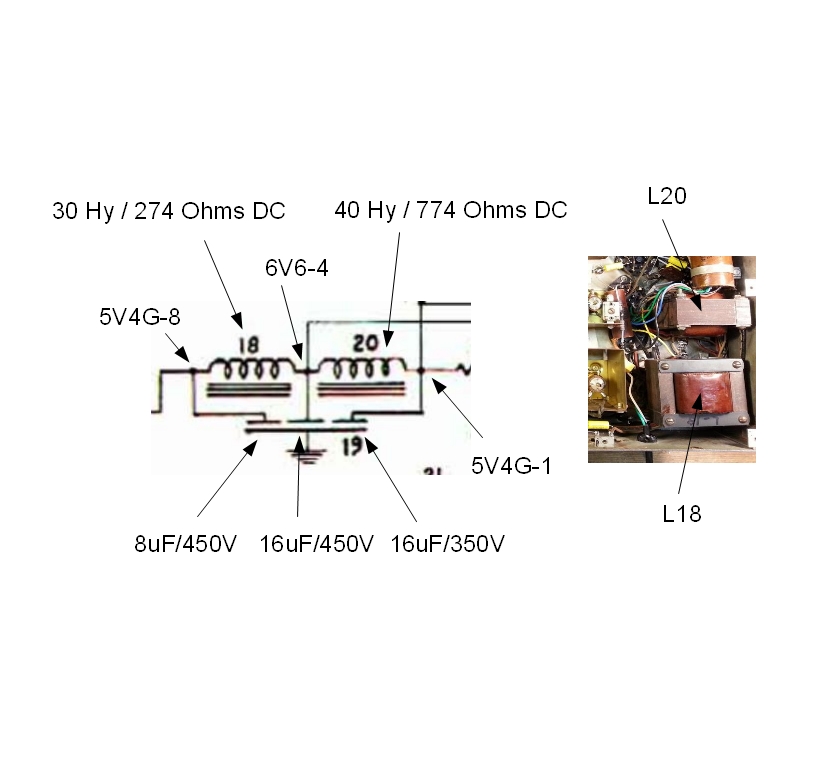
I decided to restuff the 3 section filter capacitor (C79) as well as the AF Amplifier cathode bypass capacitor (C103). Here's the filter capacitor...

Here's a diagram of the filter capacitor / choke section:
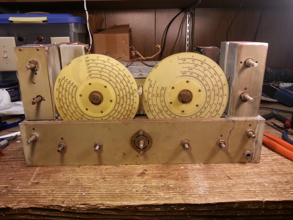
The new dials are installed! There is a split-gear with spring tensioning for the main and bandspread tuning shafts. They were very easy to adjust.

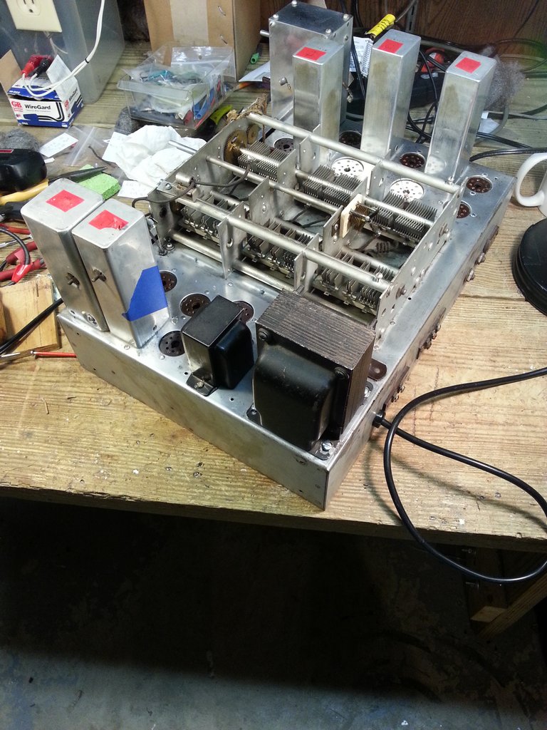
Next, I installed the two filter chokes, the filter capacitor, replaced the remaining wax paper caps, out of tolerance resistors, etc. The end result:


For my initial on the air testing I did not use any matching between the radio and my 50 ohms antennas. Signals were strong on 80, 40, and 20M. There was no activity on 10M so I pumped 5W into a dummy load and the receiver picked it up just fine. CHU Canada was loud and clear! I think I'm going to wind a 9:1 balun as the antenna expects 400 to 600 ohms and most of my antennas are 50 ohms.
I was very pleased to see the Crystal Filter / Phasing worked nicely. I'm glad I took the time to remove that sub-assembly and replace the caps and out of spec resistors inside it.
I'm not sure I'm going to do a full alignment on the radio. I want to actualy use it on the air for a while before deciding.
Here are some more detailed component placement photos for my radio (yours may be different). As should be obvious, no warranty expressed or implied in these diagrams......

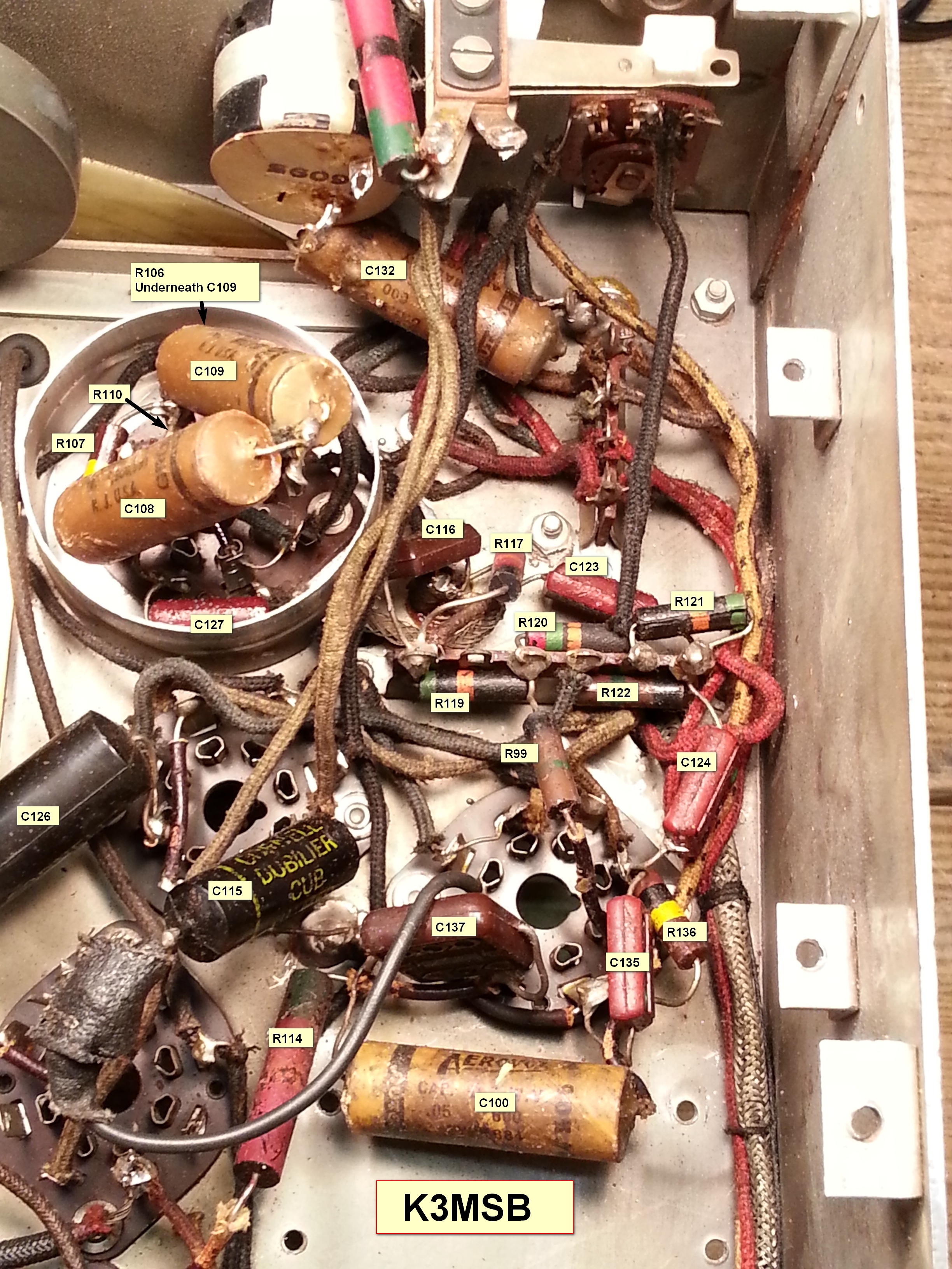
If you look at the left side of the chassis (left photo above), there are two "square" areas of components. I've called these the Front Square and Rear Square as shown below:

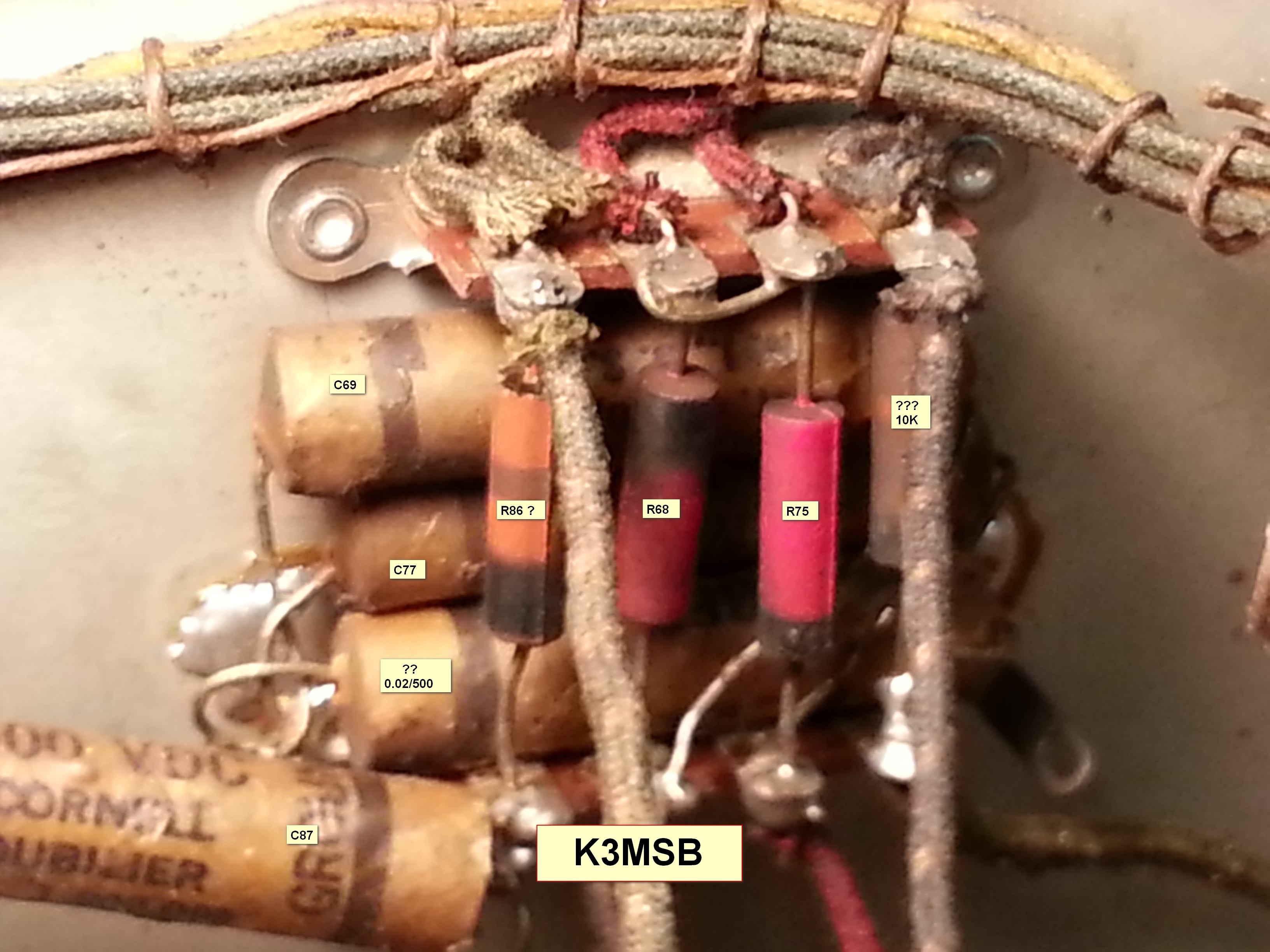
REAR Square: 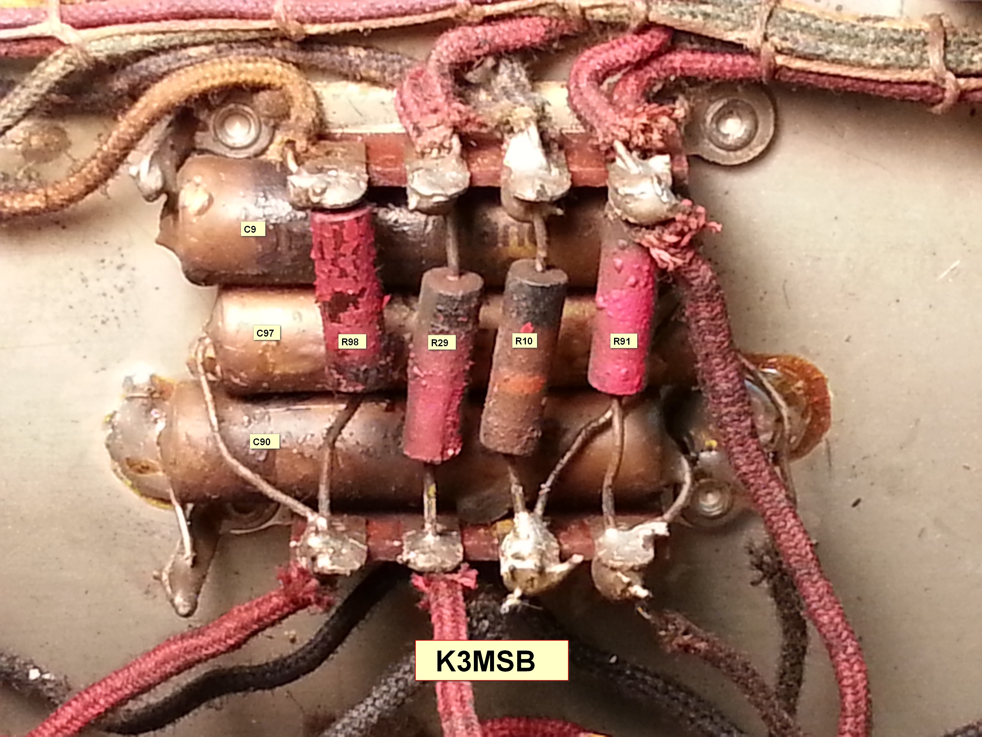

Sept 12, 2015 - 1st QSO -- K4IBZ on 20M CW!!
Great sensitivity on 20M today, and the Crystal Filter is working FB OM!
Copyright (c) Mark S. Bell 2004-2017