|
Here's my overall setup for this event. More detailed photos follow. 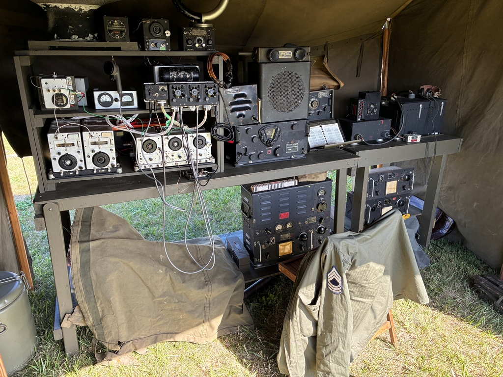
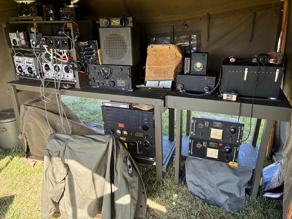
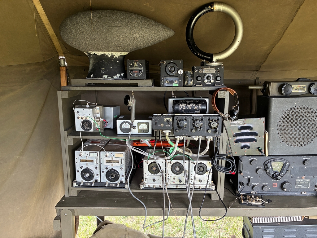
This year, before the event, I asked if anyone was going to be on the field with working radios. Two people said they would be. I managed to make 3 contacts with them (more info later). For the rest of the time, I demoed my gear by using the SCR-274N to talk to the BC-611 (and vica versa) on 75M AM. This went over well with visitors as most told me they didn't even expect my radios to work. Quite a few thought they were just props... as in show props. During the show, as I was walking around the airfield in my reenactor's uniform, I carried my BC-611 with me in plain view over my shoulder in the hopes of finding others on the field with working radios (I found no one else). This year I powered my SCR-274N with a pair of 12V 100Ah LiFePO4 batteries in series and this worked well. The batteries did not need to be recharged over night. The benefit of this was I did not need to haul my (heavy) Astron 28V power supply to the show and did not require the group's generator. Power for the BC-348 and DF radios were from a pair of standard 12V tractor batteries in series, while my John Deere tractor battery powered my ICOM IC-7300 (which was just used each morning to check the frequency of the radios – the spectrum display is great!). Having dynamotor powered radios simplifies the power requirements!
SCR-274N Command Sets
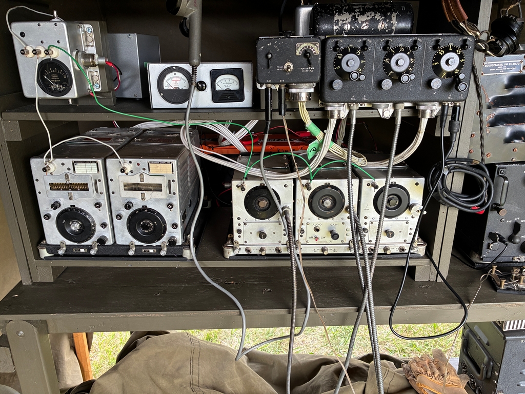
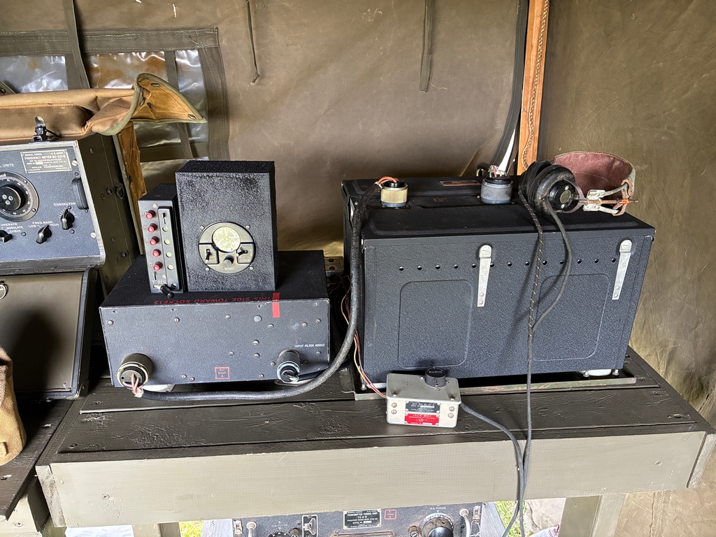
I made quite a few updates to my SCR-274N for this year. The most obvious are the two tuning cables from the BC-450A receiver control box to the receivers. The receiver on the right is the BC-454-B that covers 75M band. Since I needed relatively 'fine' tuning to get on 3885 I elected to use a local control knob on that receiver as there is a bit of backlash using the tuning cables. A working HS-33A (postwar) headset was available if someone wanted to use it. It is connected to the BC-450-A receiver control box via the CW-49534 headset extension cable. This cable accepts the PL-354 headset plug and the other end is a PL-55 plug suitable for the BC-450-A. This extension cable was necessary as the headset was not normally plugged into the receiver control box -- hopefully those intermediate boxes will be in place for the September 2026 event. The BC-450A was also connected to the 3.2 ohm LS-3 speaker via a 600:4 Ohm matching transformer (out of view behind the BC-348).
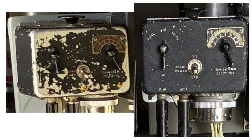
I replaced the old BC-451-A pilots control box (left below) with a nicer one.
In the photo below, the top parts shows how I previously had my FT-220-A three receiver rack secured to my display. The bottom part shows my ersatz FT-221 three receiver rack mount!
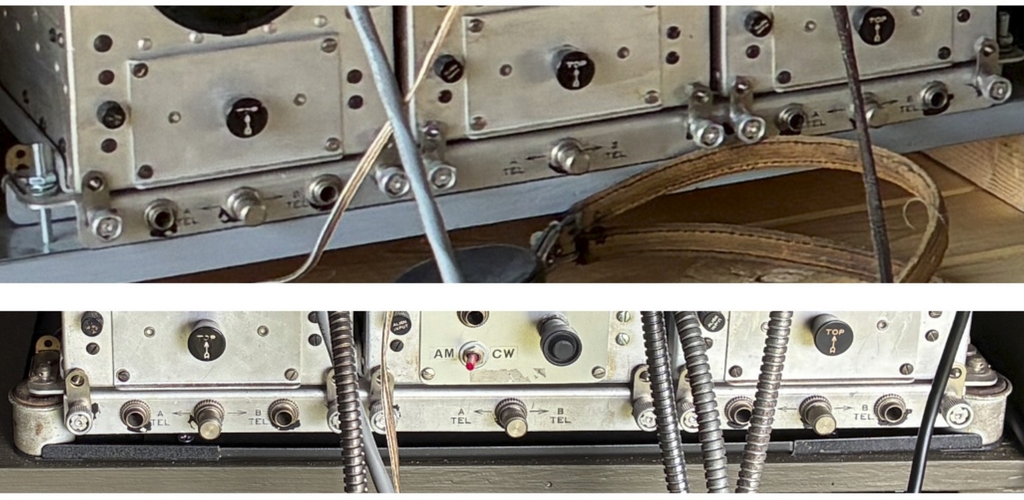
I have been trying to acquire an FT-221 mount for years. When they become available, the prices are steep and I refuse to pay them. In the spring, I realized I had a rather buggered up single unit mount in the attic. Using my Dremel, I cut it as shown in the following photo and added some angle stock I had on hand. Upon close inspection it will be obvious it's not a real FT-221, but it does the job!
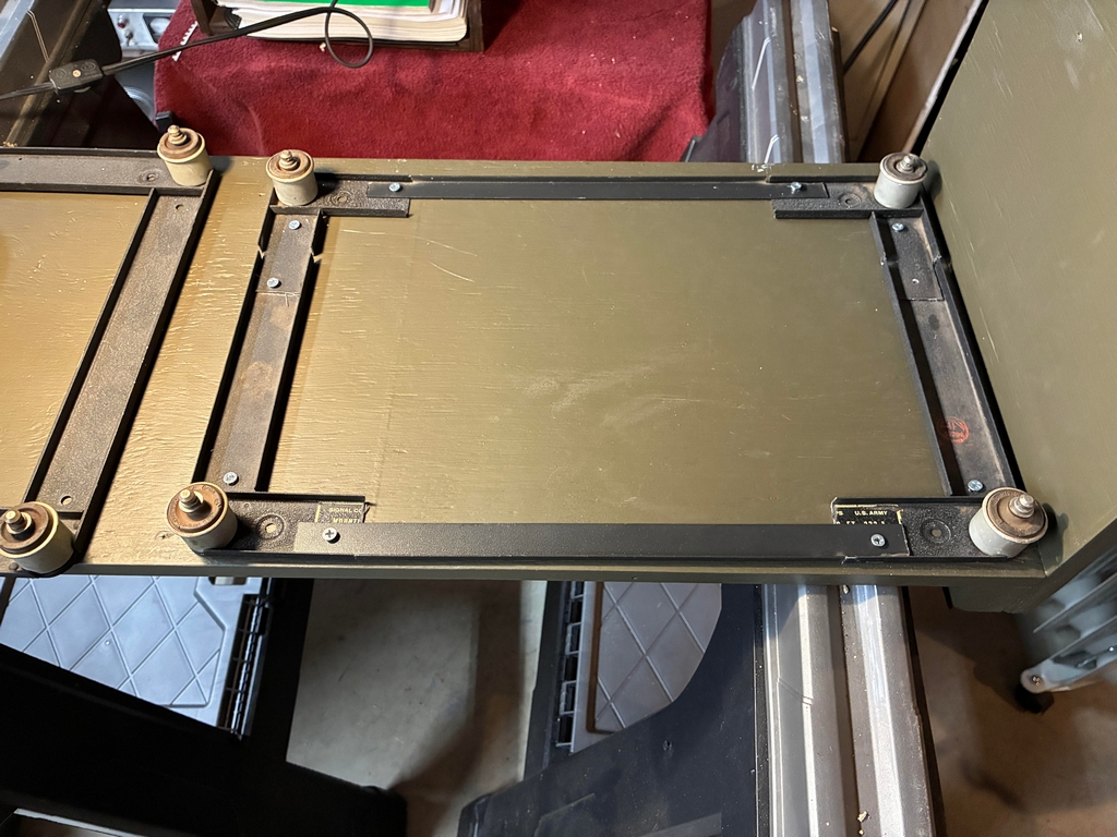
The SCR-274N performed well on 75M AM throughout the event. I made one on- field contact with it, which is one more than last year. In the future, I'm hoping that bringing working radios to the event will motivate others to also do so, as I've been told by others, on several occasions, that they don't bring working radios to events as no one else does! DF Radios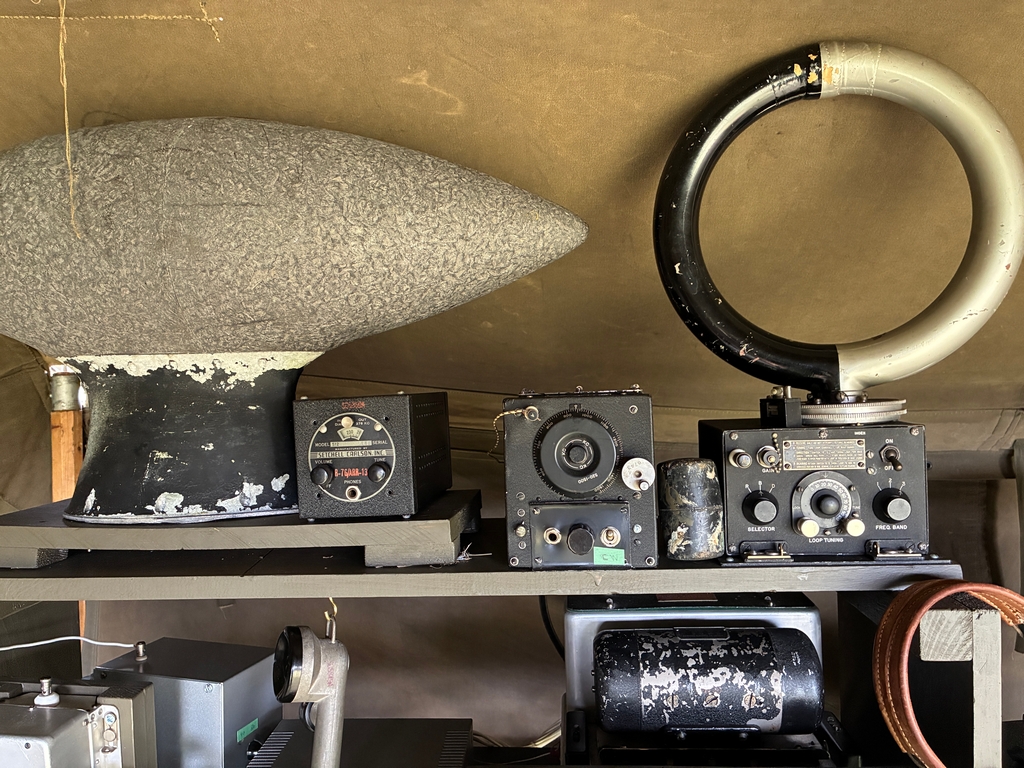
In the above photo, the two radios on the right were used for the DF demo. They are a Bendix DU-1 Direction Finding Unit feeding an ARA CBY-46145 Broadcast band (500 to 1500 Kc) navigation receiver. I had a local AM BCB station tuned in and the demo worked very well. I explained how a lost pilot would use DF to find a navigation beacon. I then told them about the CW button on the SCR-274N Pilot's Control Box and how by pressing it a ground station could tell a pilot his bearing from the station. I contrasted the differences. The "football" is an MN-36 Loop Antenna that is part of the Bendix MN-31 Automatic Radio Compass System. It is currently a static display. Before the reenactor event I tried to use a sense antenna but could not get it to work. I will have to look into this further.. Last year I had a separate dynamotor powering the DU-1. This year I realized I could pick off the HV from the ARA's connector for the DU-1 as the additional current requirement is very low. Worked well.
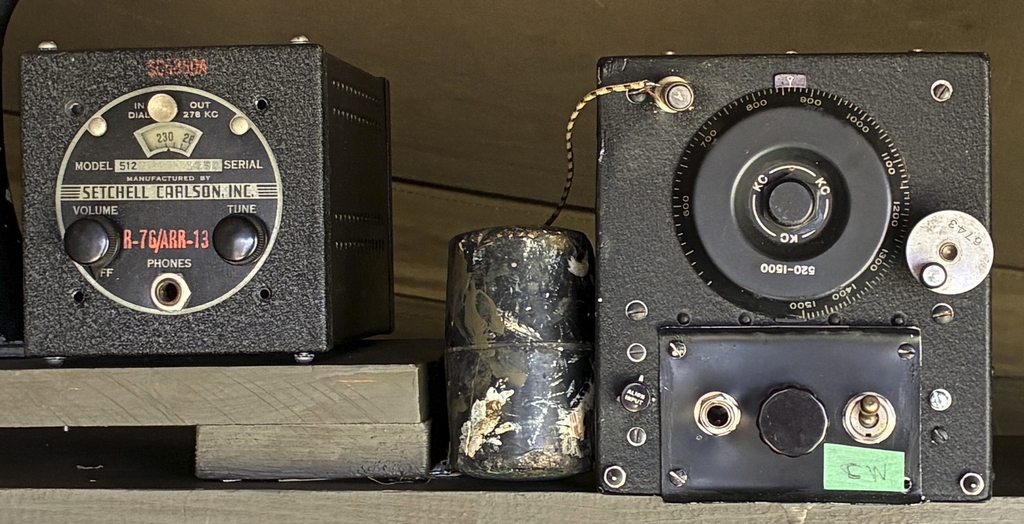
I had a Setchell Carlson LF receiver (above photo) on static display and explained how this radio was used to provide lateral guidance when flying the Low Frequency Radio Range. I took the opportunity to explain what the Adcock Range was and how the pilot knew that he was on coarse via the blending of the 'A' and 'N' signals. Also in the above photo, note the rubber mallet. The antenna relay in the 75M SCR-274N receiver would occasionally get stuck, and I had to gently whack the front of the radio. This was a hit (pardon the pun) with every guy that came into the tent!
The following photo shows the BC-611, BC-348Q, and BC-221.
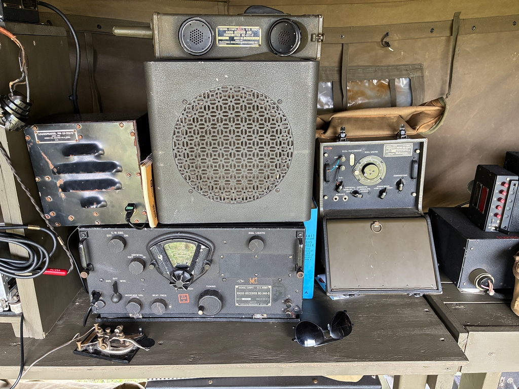
BC-611
I explained to visitors how this Frequency Meter was used to tune the various radios on the aircraft to the correct frequencies before a mission.
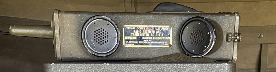
Me with the BC-611. The Bantam Trailer in the background is mine. 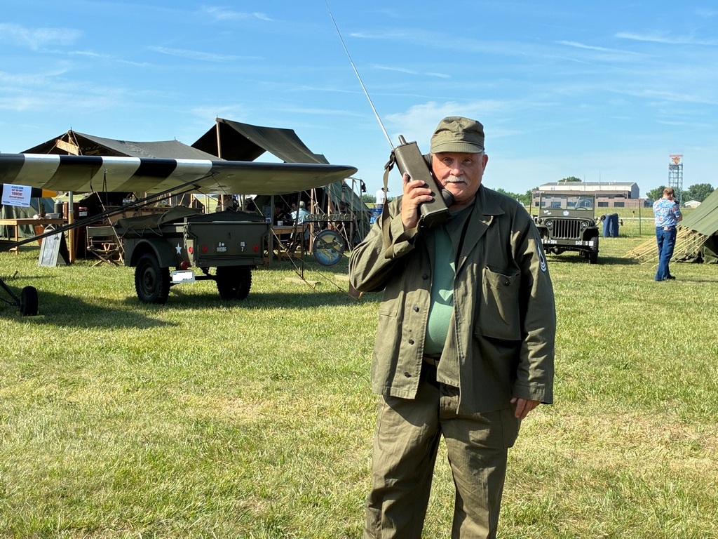
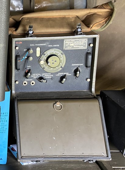
BC-221
I explained to visitors how this Frequency Meter was used to tune the various radios on the aircraft to the correct frequencies before a mission.
SCR-287 Liaison Radios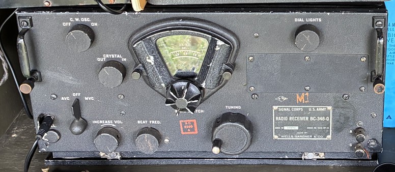
...and the BC-375 transmitter. Two tuning units are shown on the right. 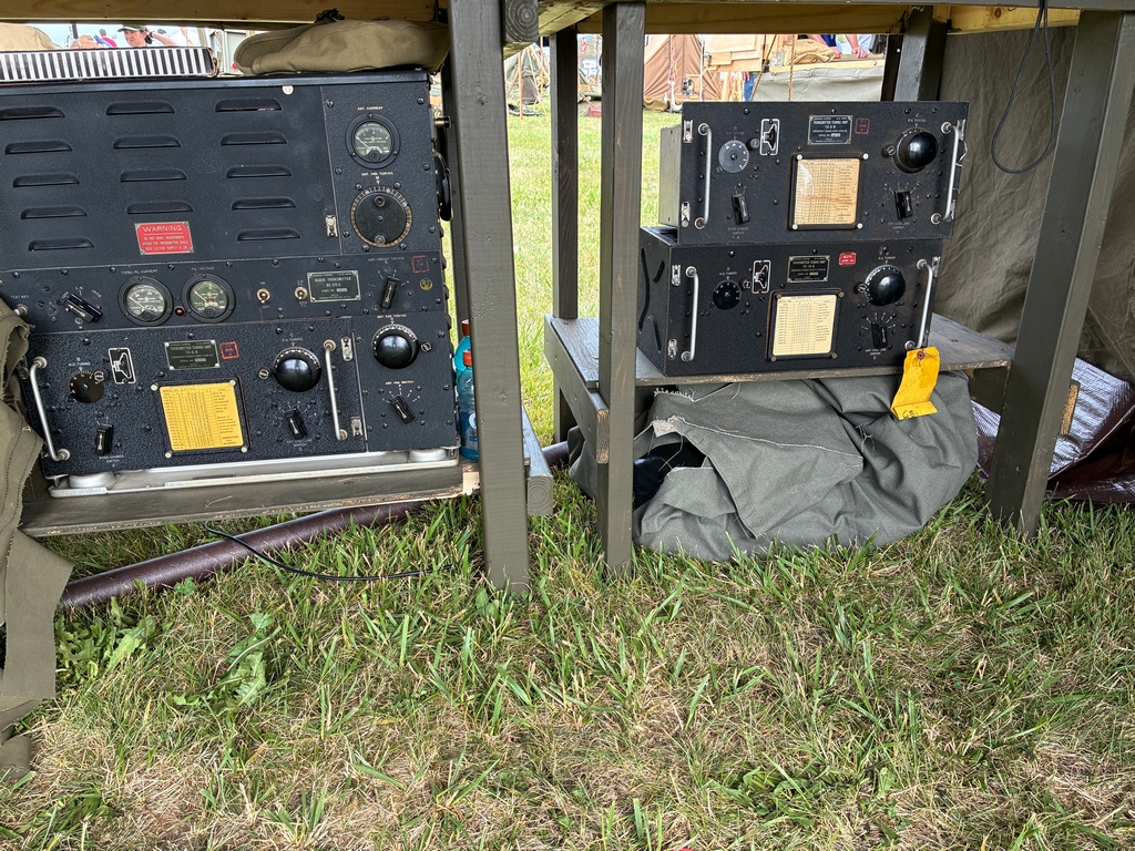
The BC-348Q was running, but the BC-375 was static display only. With the on field constraints I have to work with, there is no practical way to power the transmitter. SCR-522 VHF Transceiver
The transceiver looks to be in pristine condition, and came out of the original shipping box on which was stenciled “Brooklyn Navy Yard” !
Here's a photo of the pilots control box (left) and the “Unit” (right). That's all the shipping box for the device says.... “Unit” ! 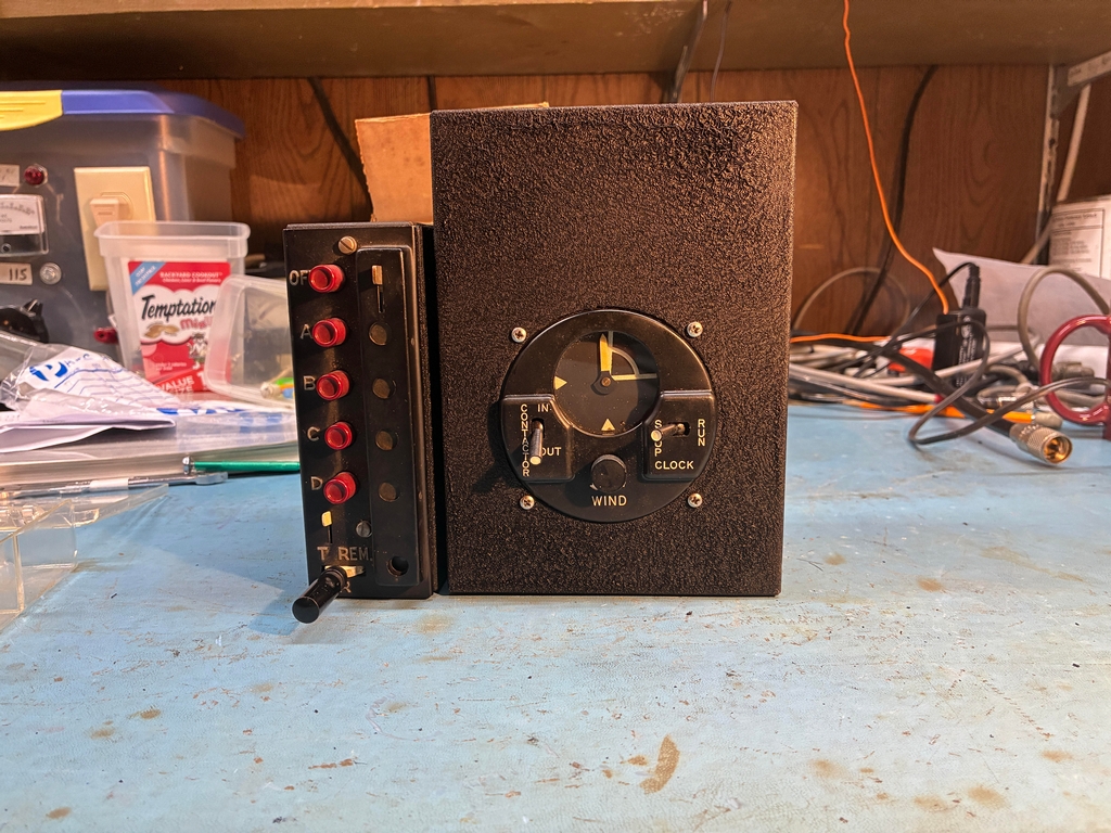
The pilot's 4 channel control box and the “Unit” were located in different places in the cockpit. I mounted the “Unit” into an old Radio Shack project box and bolted it to the control box. This was my first attempt at using black crinkle paint; the result was OK, but I need more experience to get a nicer finish. So, what is the “Unit”? It's the BC-608A Contactor Unit, nicknamed “Pipsqueak” by the British in the days leading up to WW II. It's basically a clock. But if you'll observe, the first 14 seconds of each minute are marked on the face of the unit. When the “Contactor” switch is in the “In” position, and the Clock switch is in the “Run” position, the radio will transmit on channel D during the 14 second interval, overriding pilot communications. During this 14 second interval, British ground stations would DF on the transmitted signal to get an accurate position of their fighter aircraft. This was highly important for the British in the very early days of WW II.. Knowing the position, velocity, and altitude of the German aircraft was only half of the problem. The British needed to know the position of their own fighters (Spitfires, Hurricanes, etc), so that combined with the performance characteristics of the fighters, and prevailing meteorological conditions (winds aloft, temperature, humidity), a least time to intercept solution could be determined. In other words, get the British fighters to the German aircraft in the shortest time possible. As the British Mk 1 IFF system was initially deployed in late 1939, the Pipsqueak was only used during the very early months of WW II. How well it performed is still up for debate.
|