Click on any image for a larger version...if it exists....
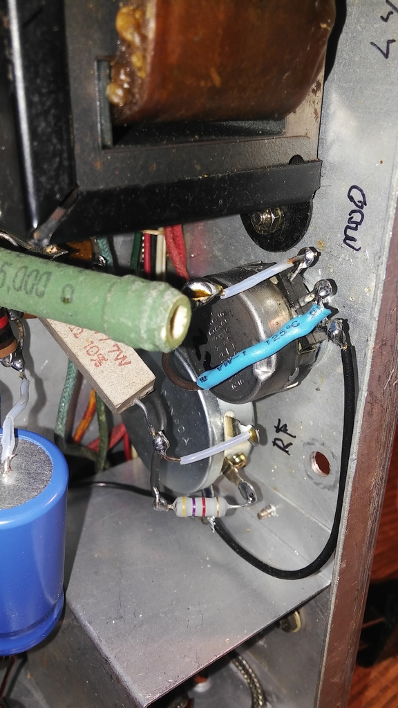
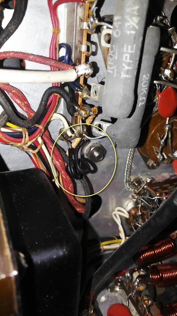
| The Chernobyl resistor is R3 which is an 18K 2W resistor. The failure mode is that it heats up and goes bad. It is recommended to replace it with at least a 5W resistor. I had a 20K 12W resistor on hand so that what I used. |

|
|
The goal is to snip R3 closest to the resistor body and then attach the new resistor inside the VFO compartment
or add some wires to the wire stubs, pass them through an unused chassis hole in the VFO compartment, then mount
the new resistor under the chassis. I chose the latter option.
As I attempted to solder the wire to the stub from the confluence of R3 and R5, the existing stub fell off -- crud. I then attempted to solder the next wire to the stub from the OA2 socket, but it fell out of the solder lug upon heating -- crud. I think my Valiant was one of the kit ones..... Try as I might, I couldn't see how I could get a soldering iron to that lug. I noticed that there were not a lot of wires attached to the 0A2 socket, so I decided to unscrew the socket and bend the entire socket downwards -- carefully..... |

|
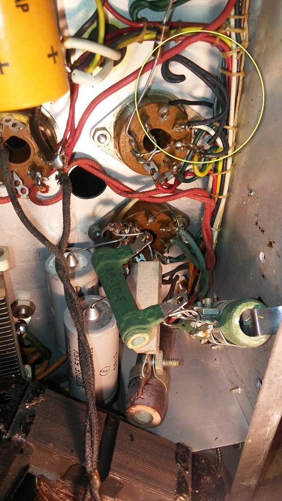
| That worked out fine. After soldering the new wire, it took careful prodding to get the socket back into place. The following picture shows the two yellow wires the go underneath the chassis. |

|
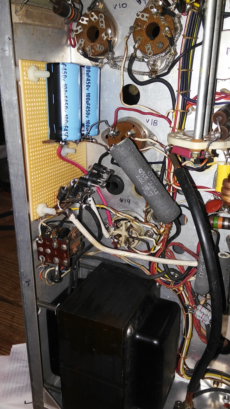
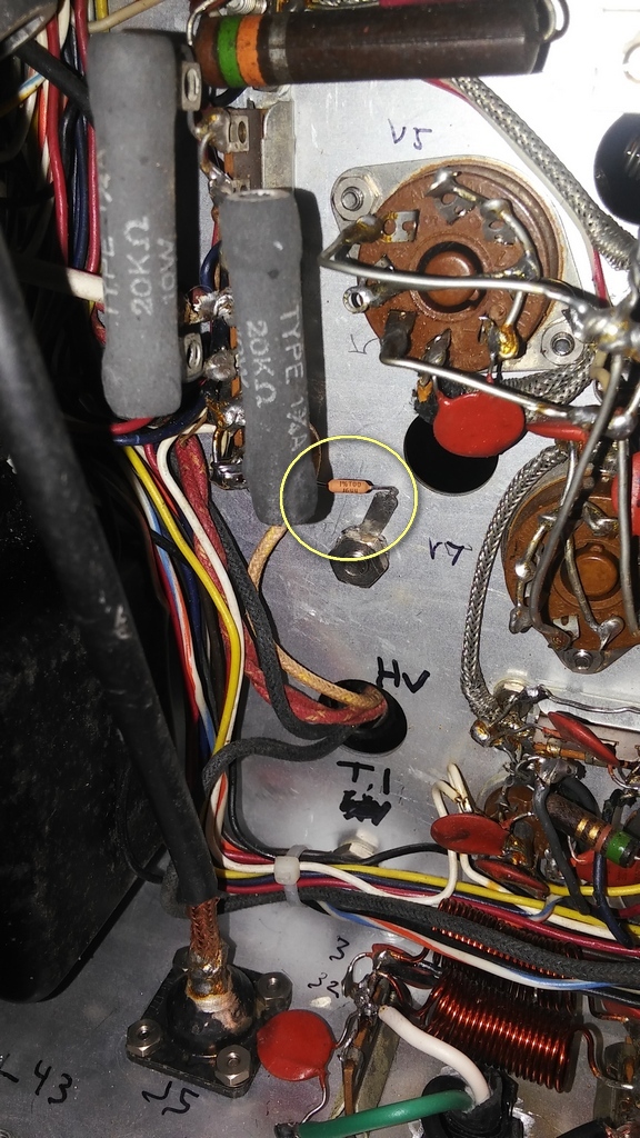
| Here's the new R3..... |

|
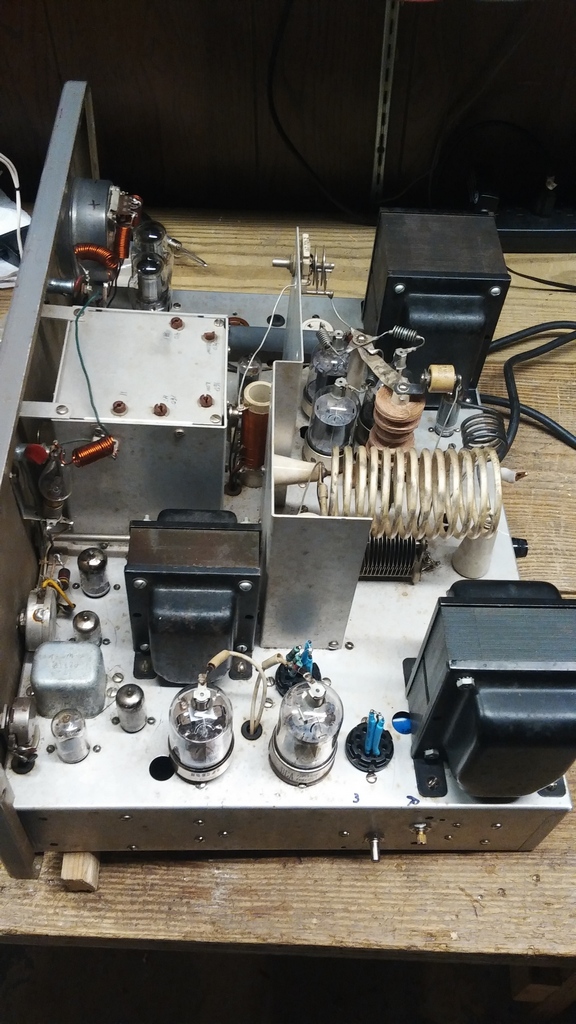
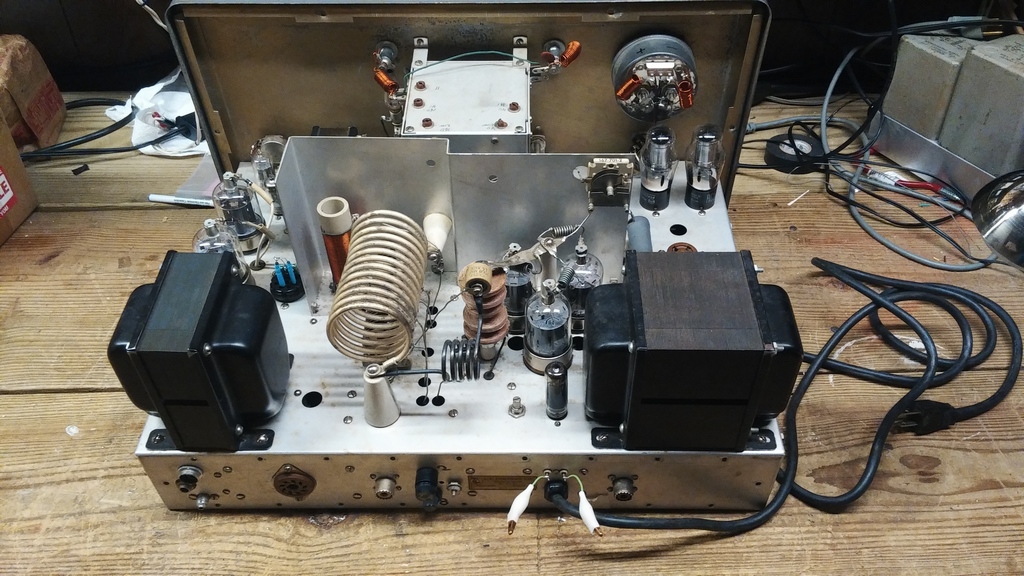
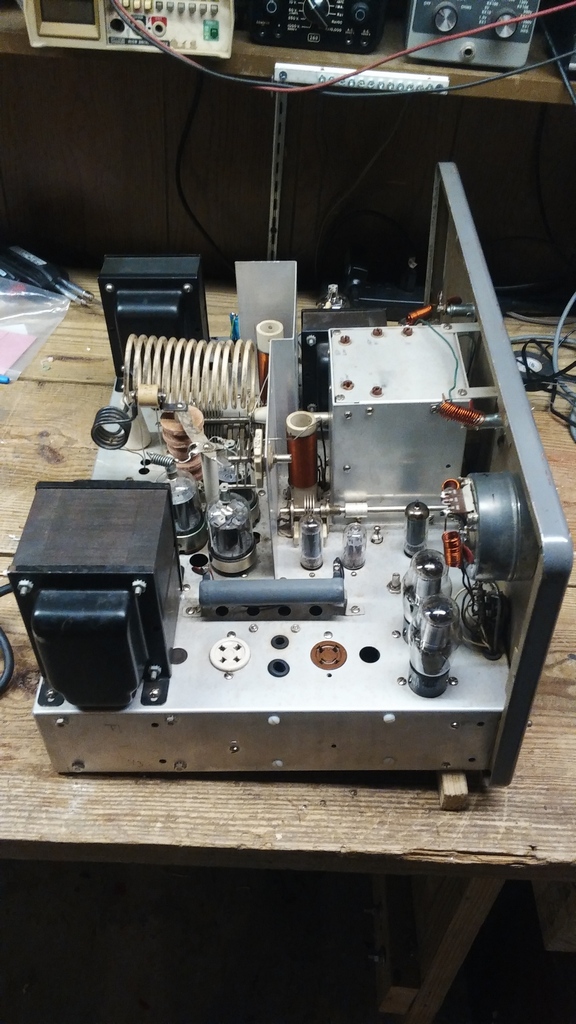
Solid stating the HV, LV, and Bias power supplies. No dropping resistors were used for the HV or Bias supplies.
|
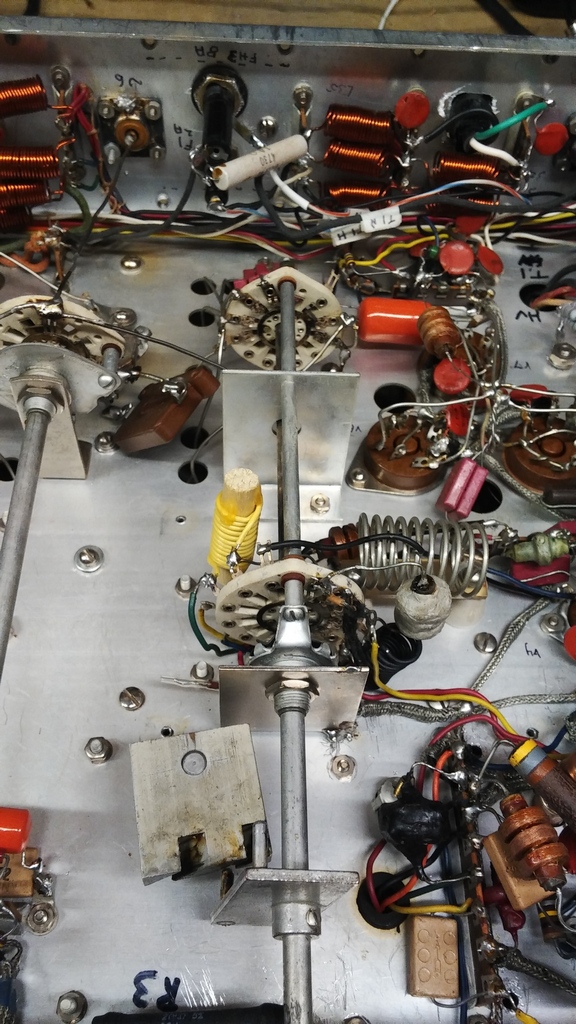
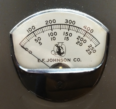
The Valiant's meter has 20 ohms internal resistance and 5 mA full scale deflection.
It will therefore drop 0.1 volts full scale. The two most "interesting" shunt resistors are the 0.404 ohm modulator shunt resistor and the 0.202 ohm plate current shunt resistor. Some say leave them alone, some say replace them. Since they tend to be inaccurate, I chose to replace them. Read on...... By the way, remember to put diode protection across the meter! |
|
|
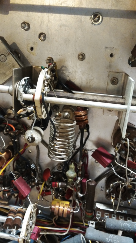
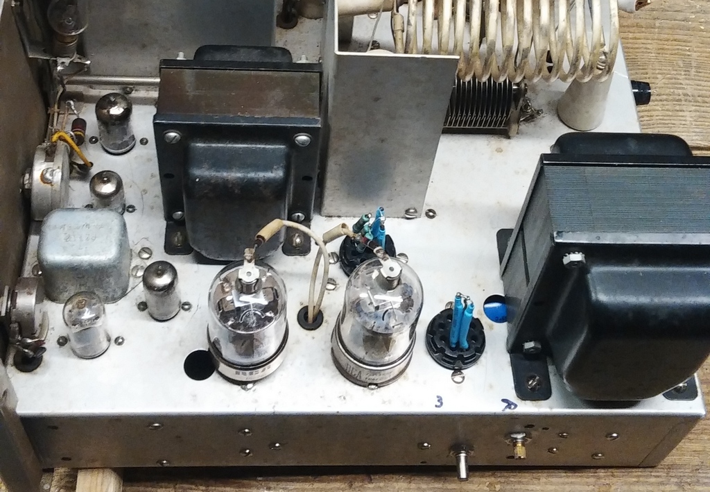
The 0.202 ohm plate current shunt resistor is located to the upper right of T1
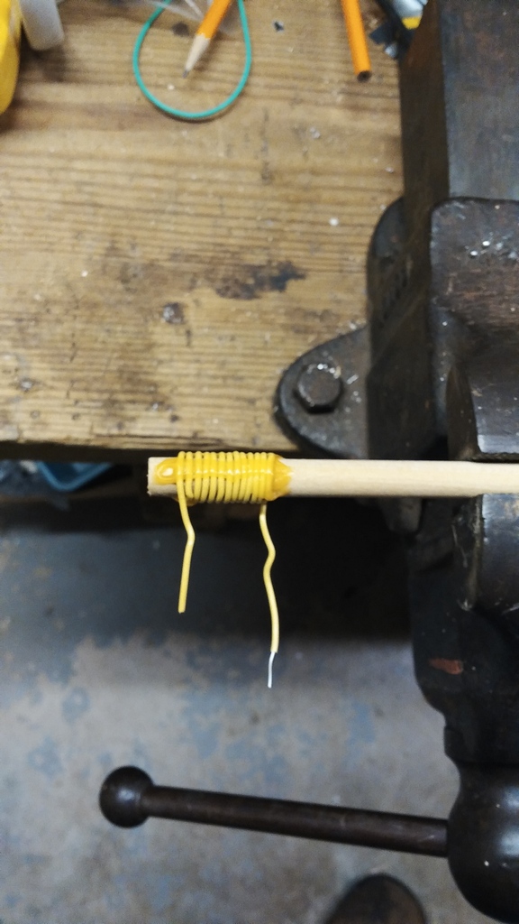
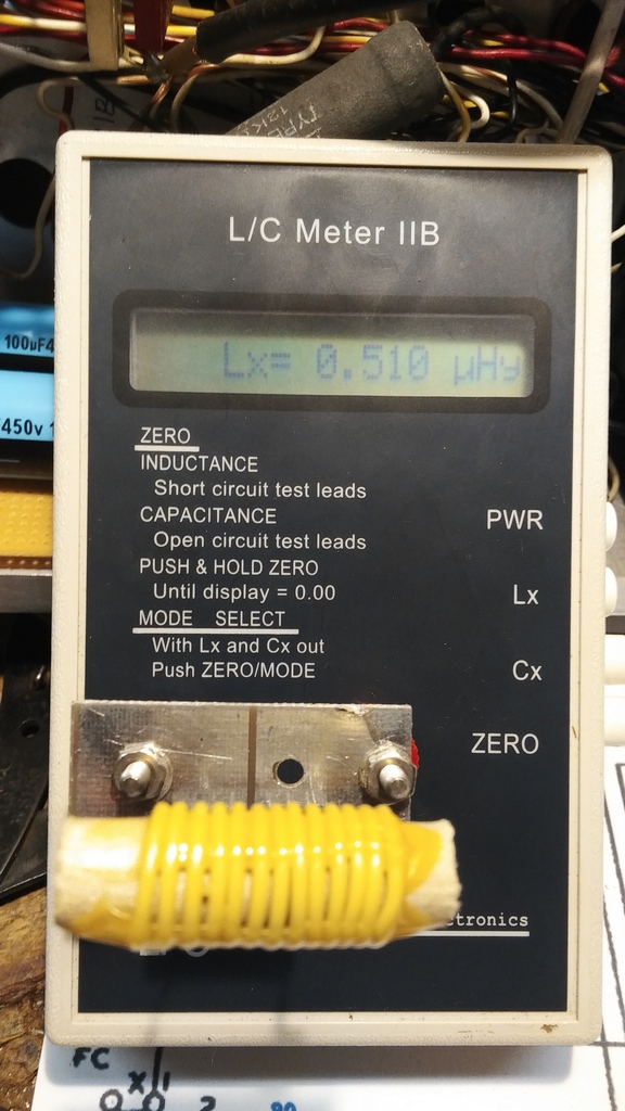
This shunt, as well as the modulator shunt (see below), were made by using accurate lengths of resistance wire. The kit versions of the Valiant were notorious for having inaccurate shunts which is why I decided to replace both. For the plate current the 0.202 ohm shunt is in parallel with the meter's 20 ohms internal resistance. The total resistance will be 20(0.202) / 20.202 = 0.2 ohms. Full scale on the meter is 500 mA => Voltage drop across the meter is 0.5A x 0.2 ohms = 0.1 V. At 500 mA full scale, the current though the shunt will be 0.1V / 0.202 ohms = 0.495A The minimum power rating of the shunt resistor is be 0.202 * 0.495 = 0.1W. It is CRITICAL that this resistor be VERY WELL grounded. |
Old |
New |
|
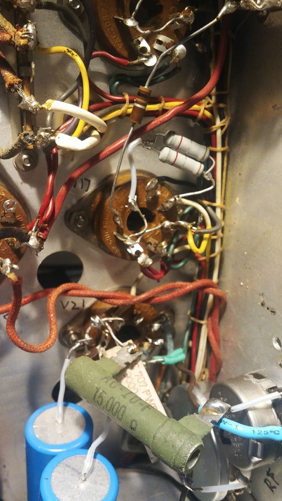
The 0.404 ohm modulator current shunt resistor is located on socket XV-17 which is under L44.
It is CRITICAL that this resistor be VERY WELL grounded. |
Old |
New |
|
I ran into some issues while replacing the plate current shunt resistor which resulted in a very high plate current meter indication.
It was suggested that I measure the plate current externally. The end result was the following modification to the plug for J8. Plate current is picked off by inserting an RCA plug/jack into the normal jumper between P8-2 and P8-6. I have several DC meters that I can then insert when external Ip monitoring is desired. Be careful - there's 600+ VDC on those two pins, which is why I didn't want to use alligator clips. Plate current is read in CW mode. In AM Mode the external meter will read the combined plate and modulator currents. Note: if you have not performed the mod for the V9 and V10 regulator current, the plate current indication will be about 30 mA higher than the real value in AM mode. Low Voltage can be observed by adding a wire to P8-4, putting a VTVM etc between it and ground. Again, be careful; there's 300+ volts at the end of that wire. |
New |
|
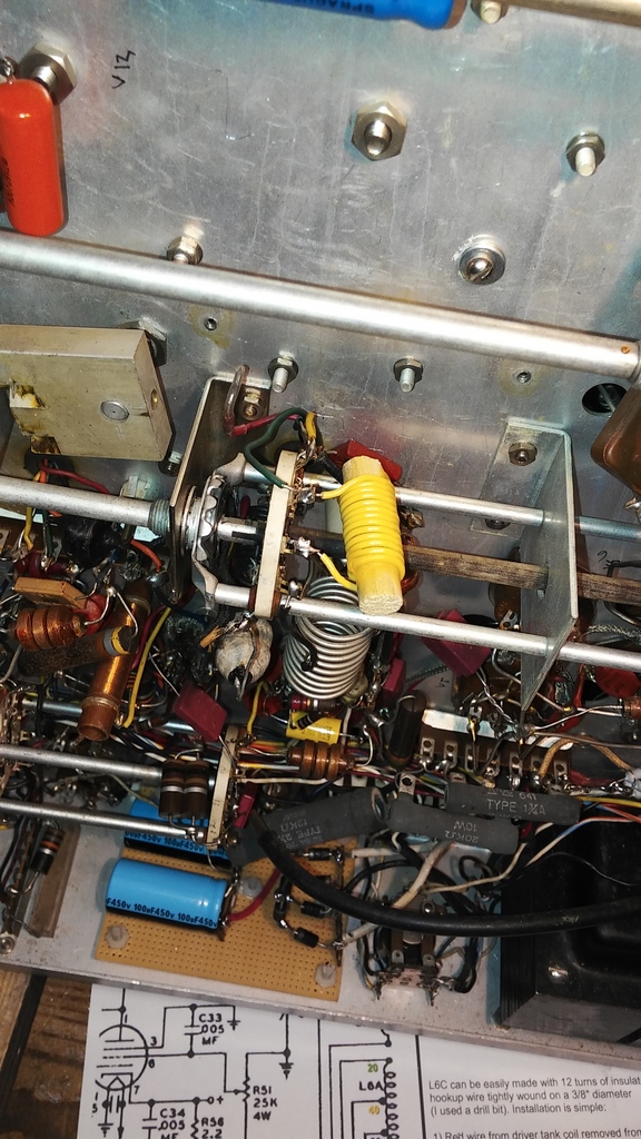
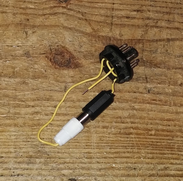
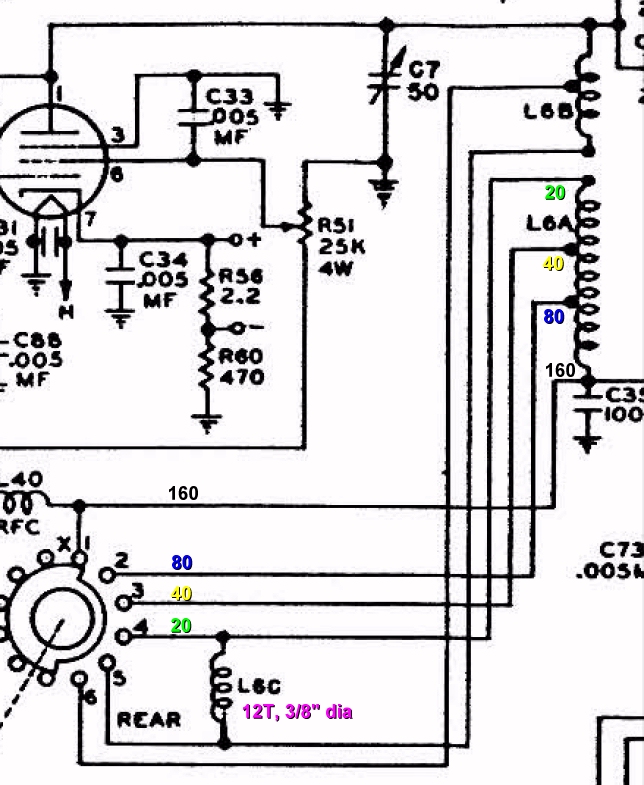
"Suffering from low drive? Several Valiants have come across the workbench with this issue, so I decided to share the secret to restoring that Valiant libido to where it should be and with only minor invasive surgery! "Valiant A", as we'll call it, had nearly no drive on 20M. "Valiant B" had widely varying drive on the upper bands. In both cases, the 5763 would not be able to create the specified 7.5 mA of PA grid current, and high settings of the DRIVE pot would cause saturation. As it turns out, later factory wired Valiants and all Valiant IIs have an additional coil "L6C" mounted to the SW3A band selector switch which increases the inductance and Q of the driver tank circuit. L6C can be easily made with 12 turns of insulated solid conductor hookup wire tightly wound on a 3/8" diameter (I used a drill bit). Installation is simple: 1) Red wire from driver tank coil removed from terminal #4 on SW3A. Insulate the end as it will not be used. 2) Green wire from driver tank coil moved from terminal #5 to terminal #4 on SW3A. 3) L6C installed between terminals #4 and #5 on SW3A. The attached schematic shows the change of heart the E.F. Johnson engineers had late in the original Valiant production run that became the norm for the Valiant IIs. You should see an improvement in drive for 20M and up or your money back. Not recommended for 11 meter operation. Use as directed." Clark N1BCG (Valiant Guru) Reprinted with permission..... |
|