|
Here are some comments about my recent repair of a Zenith Transoceanic short wave radio. More than a technical write up, it also makes some observations about managing the expectations of a customer who has no radio knowledge. He wants to plug the radio in, turn on the radio, and expects music to come out! |
|
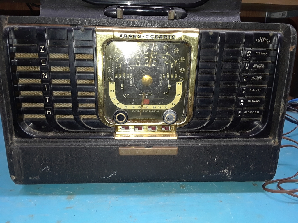
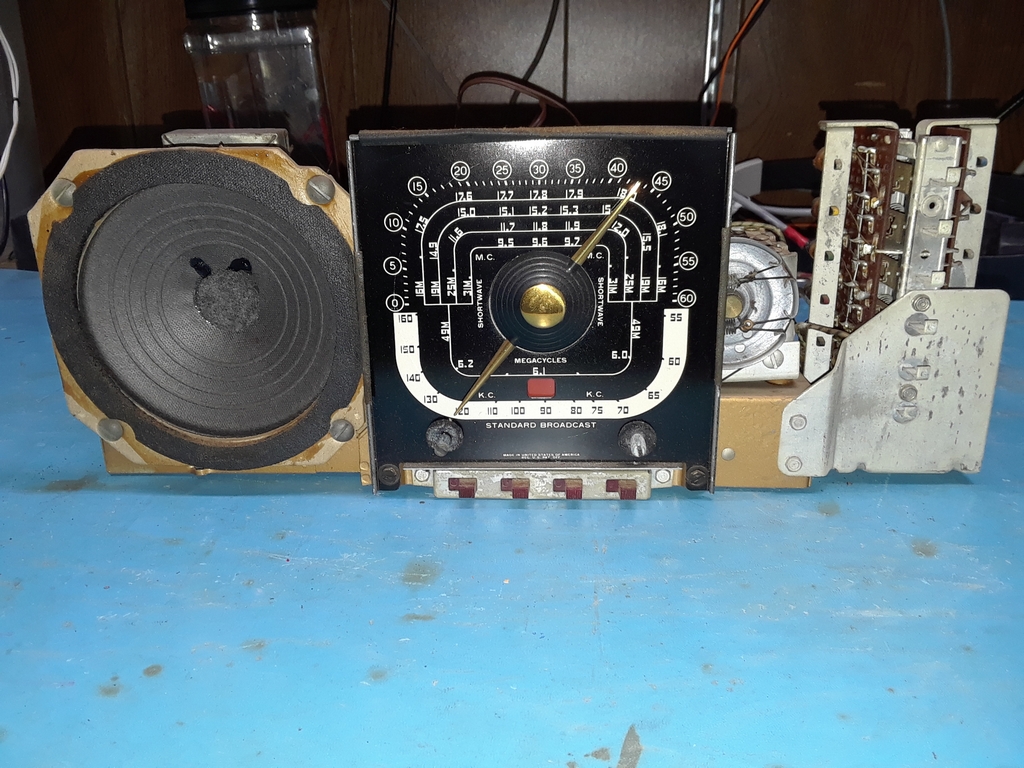
The Transoceanic is a well know 1950's era AM/Short Wave AC/DC portable radio with a typical 1.4V tube lineup: 1U4 RF Amplifier, 1L6 Converter, 1UF IF Amplifier, 1S5 Detector, AVC and AF stage, and a 3V4 Audio Amplifier. Total power consumption when run off of 110 VAC is just 10W. This is about 1/3 of the power consumption of the typical 'All American 5' tabletop radio of that era that only covered the AM broadcast band. There is a huge amount of well written information on this radio currently on the web, and I'm not going to repeat it here.
Unfortunately, if you want to see the warm glow of vacuum tubes, you'll be disappointed peeking into the back of this radio as those 1.4V filament tubes don't glow much at all.
|
|
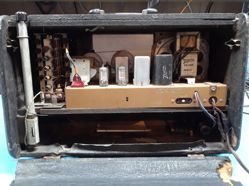
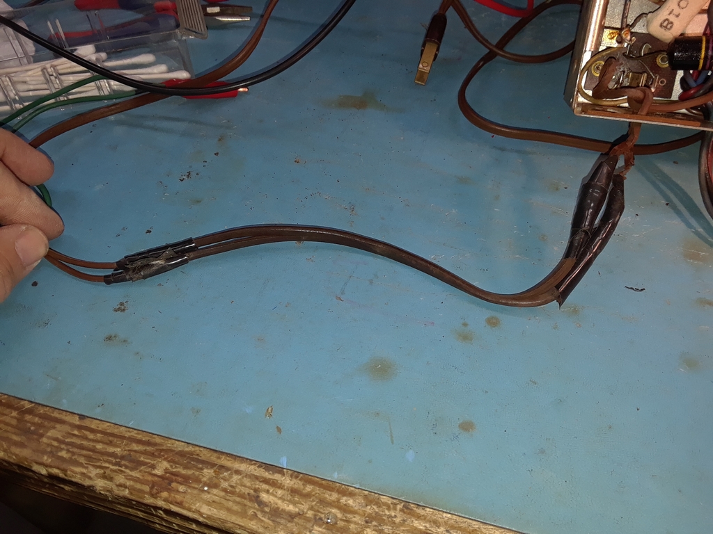
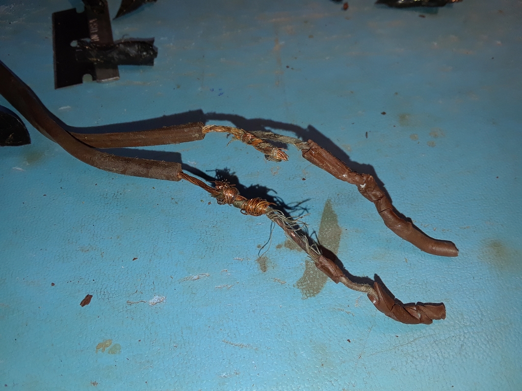
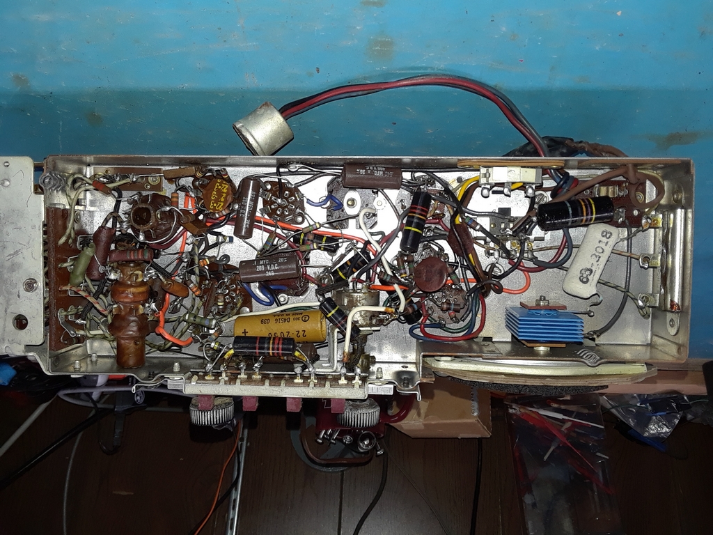
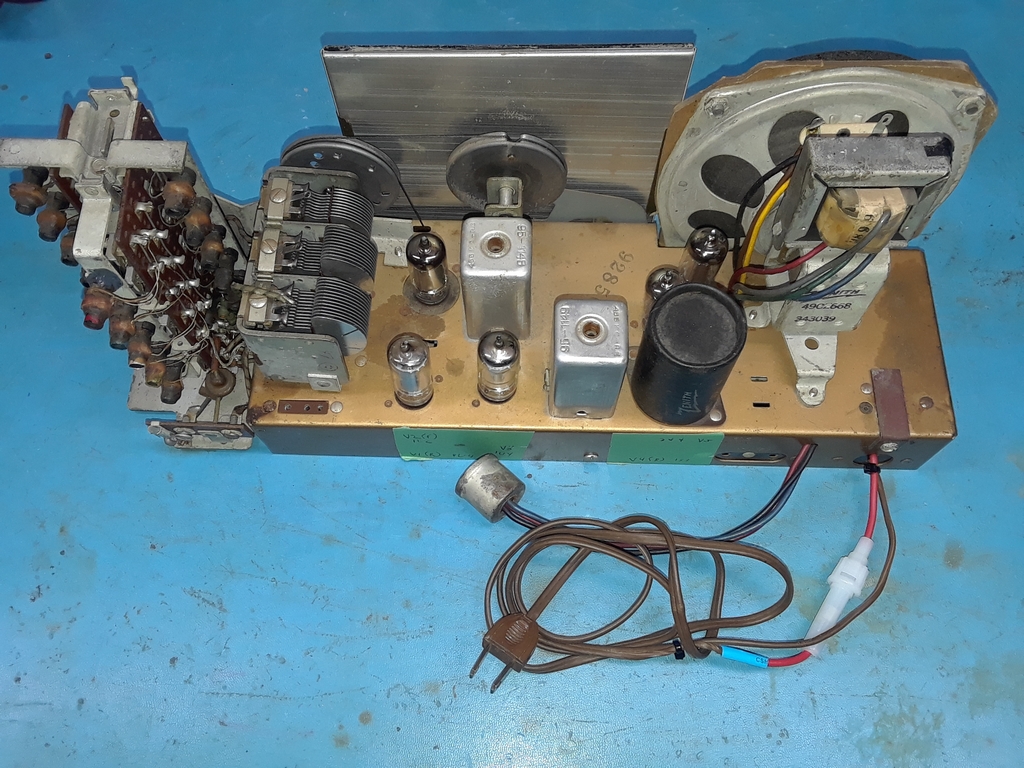
I have been restoring vacuum tube radios since the late 1990's, the overwhelming majority of those radios being amateur (Ham) radios and WW II vintage radios (USAAF and USN). I've worked on several first generation hybrid transceivers as well. When I work on radios that are not mine, they are almost always for friends that are either hams or have a radio background. Why is this important? I will share experiences as a pilot taking a non-pilot on their first airplane ride. You prepare them as best as you can. After an almost perfect flight, they'll tell their friends you almost killed them! After a flight where you did something bone-headed that could have turned out bad, they'll tell their friends it was a great flight and you're almost as good a pilot as Chuck Yeager! If you're a fellow pilot, you have at least one T-Shirt for this in your closet! Rarely do I work on radios for people that are not technically oriented. In light of the above paragraph, I realized that managing customer expectations was going to be important while working on this Zenith. The customer, a friend at church, picked up this radio at a pawn shop several years ago and asked me to look into it as it didn't receive very well and operation was intermittent. His primary desire was to show his children and grandchildren how an old tube radio worked and sounded. He was interested only in AM broadcast band reception. Short wave reception was not that important. So, this is a repair job, not a restoration job. As readers that work on radios are well aware there is a big difference between restoring a radio and repairing a radio. There are multiple levels even in the definition of 'restoration'. The price to work on the radio increase greatly from repair to top end restoration. For my friend, I wanted to provide a repaired radio of acceptable performance within the constraints of low cost. This version of the Transoceanic is a commonly available radio that is in average condition. This year (2024) I've seen these and similar class radios at Hamfests selling for $80 to $90, advertised as fully working. Most didn't sell. This factored into decisions about how to repair the radio and when to stop from going deeper in the repair process. Initial inspection of the radio showed that it had gone through at least two previous repair cycles as illustrated by markedly different wire styles and questionable repair practices (for example, using two 500K resistors in series to replace a 1M resistor with the connection between the two resistors protruding such that it almost made contact with the chassis. It should be noted that this radio has a floating B- bus and it is not the chassis ground. Contact between the B- bus and chassis ground is via a single RC filter (the R and C are of course not co-located in the chassis). As can be seen in the following photo, the line cord wiring left a bit to be desired! As my one friend said after seeing it....'What did the fire Marshall say after the house burned down?' The cord was replaced with a modern non-polarized fused line cord. It should be noted that the manual says to reverse the plug in the 110V AC wall socket to reduce noise and hum. I found this made no difference.
|
|
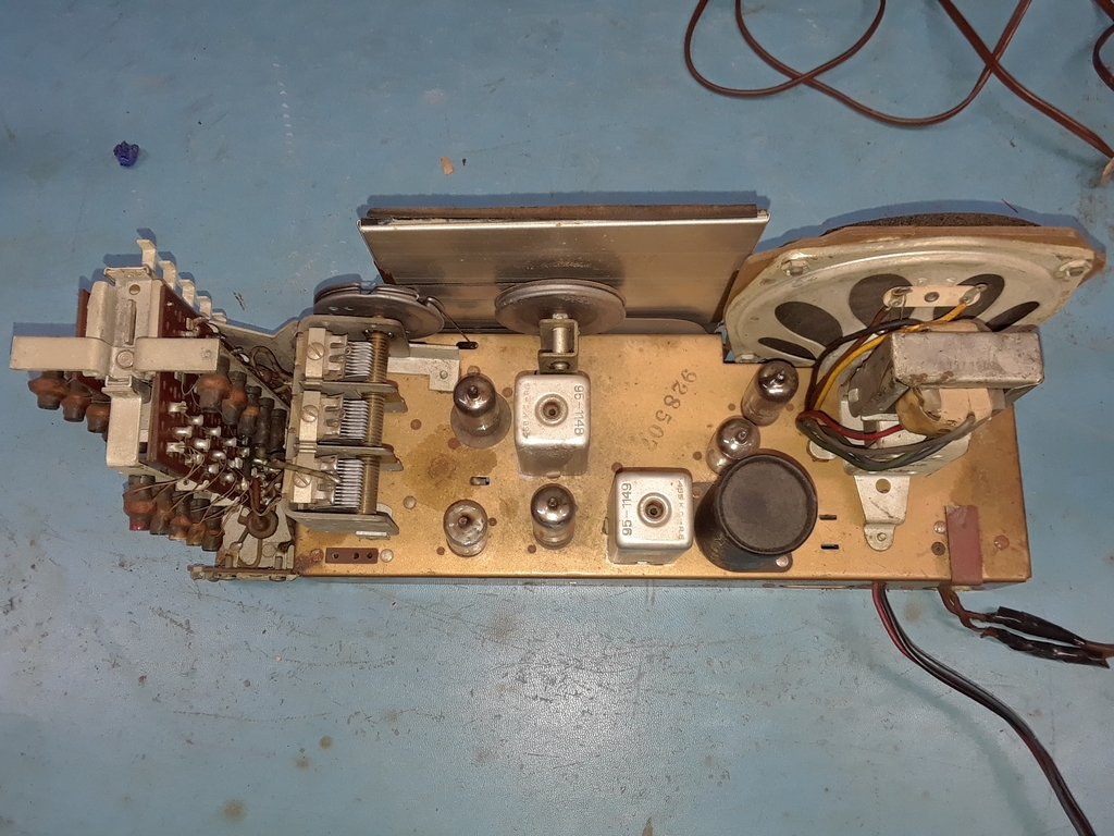
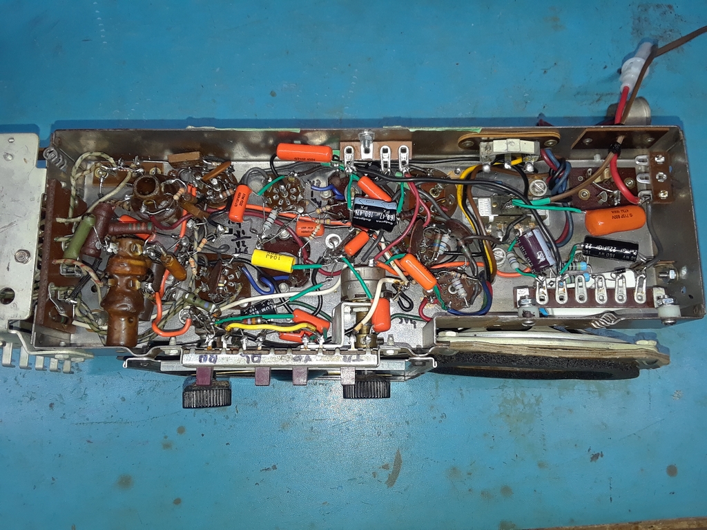
Before and after photos are shown below. |
|
The Selenium Rectifier and the 130 ohm 3W surge limiter resistor R30 were replaced by a modern silicon diode and 150 ohm 6W resistor combination. Both 950 ohm halves of the 5W dropping resistor R31 were almost 100% out of tolerance and they were replaced with a pair of 1K 10W resistors. I did not have these 10W resistors in stock so had to order them. The resistors are about $1 each, but you pay $6 shipping. This is why I ordered a dozen of them – no change in shipping cost and I have them in stock. All black beauty wax paper capacitors and electrolytic capacitors were replaced. One of my guiding principles of radio work is there are only two kinds of these capacitors: those that ARE bad and those that WILL go bad and take something made of 'unobtainium' with them. I elected to not re-stuff the four stage electrolytic capacitor on the chassis, but rather use four discrete capacitors under the chassis. This was because I did not have four suitable capacitors all of which would fit in the capacitor housing. This worked out well, but took up more under chassis real estate than desired. If I had to do it over again, I'd put a few in the original capacitor housing and the rest underneath the chassis. Yes, I could have ordered suitable capacitors, they are not that expensive. But, you add on another $6 shipping that has to be passed on to the customer. All out of tolerance resistors were replaced except a pair of 15M resistors. I didn't have them available and they were not that far out of tolerance to matter. Again, each costs below a dollar but you have to pay shipping. Shipping is one of the reasons I buy 'a bunch' of a part when only one or two is needed. Their ain't no more Radio Shacks to go to for parts when you need them..... The radio did not work at all in the lower part of the AM Broadcast band (below about 800 Kc) and did not work well on the lower ranges of the short wave bands. I thoroughly cleaned (compressed air / DeOxit) the dirty main tuning capacitor as well as lubricated the rotor ball bearings. This had no effect on the issue. I then noted that the capacitance went to zero around the start of the dead zone and, as then expected, found the rotor to stator resistance went to zero at the same point. Obviously this was due to some of the rotor fins of the three gang tuning capacitor shorting to the stators. . Closer inspection showed physical damage to all three rotor gangs. By carefully observing the point in the tuning when signal loss occurred I was able to see (barely) where the rotors were coming into contact with the stators. Using a razor blade and small screwdrivers I was able to bend the rotors so that the issue was mainly solved, with only a bit of scratchiness in the very lower part of the AM broadcast band. Was this the right call? Had this been a full up restoration the tuning capacitor would have been completely removed from the chassis. Doing this would have meant working in some very packed areas under the chassis and restringing the dial cord. Based upon the customer's expectations I did not think this extra work was warranted. Also, in our area, most of the AM Broadcast stations are above the lower part of the band. Alignment was simple and straightforward, the only piece of test equipment being needed was a signal generator. Quite a few of the coil slugs for the shortwave bands were locked in place and gentle rocking with an alignment tool would not dislodge them. Since the customer said short wave was not that important, I elected to leave the coils alone as breaking them would have cased further issues. For DC Battery use, the 110V wall plug is plugged into a switch atop the chassis. This is a mechanical switch and the piece of internal contact metal was making very intermittent contact. I tried to bend the metal contact without much success. Since this radio will never be used on battery, I bypassed this switch when working the power section. It would not surprise me to learn that some readers are stunned that I drilled some holes in the chassis to mount terminal strips. Like I said, this is a common radio in average condition. It's a repair job and not a restoration job. None of those holes are visible unless you remove the chassis from the cabinet. In this case, I felt comfortable committing radio sacrilege..... After work was completed I spent several evenings testing the radio from my home. I live in a small valley that is adjacent to the valley formed by the Susquehanna River, which means my horizon is about 45 degrees in every direction and I've found this can impact reception of close in AM broadcast stations; ground wave has trouble making it down here.... AM Reception during the day is minimal with WSBA 910 in York PA coming in reliably. During the morning hours WBAL 1090 in Baltimore and KDKA 1020 in Pittsburgh could be heard. I used to live Pittsburgh; I am so glad I no longer have to participate in the rush hour road congestion that was being reported!
Morning AM Broadast Reception Clip 2
Evening Short Wave Reception 49 Meter Band Evening Short Wave Reception 31 Meter Band
Stations were received on the other 3 short wave bands (16, 19 & 25 Meters -- 16 Mc to 11 Mc) but not repeatedly as during listening trials on the above bands. These bands are more sensitive to solar activity and an X1.1 class solar flare was emitted from the sun the day before I made these videos. And, I have to admit, I am not a short wave listener (SWL) and really have no idea what SWL stations inhabit that part of the spectrum on a regular basis.
| Closing thoughts. I think this is going to be a fun radio to use during the winter months when propagation improves and noise decreases on both night time AM and short wave. Did I meet the customer's expectations? Did I provide a radio that works to his level of expectation for a reasonable cost? Based upon feedback, the answer is “Yes”. He said the radio works much better, but he has to learn to use it better. That's a superb observation from this non-radio friend! I don't much care what the manual says, you need to have the telescoping aerial extended and the wire antenna out and stretched across the room. As we hams always say, you need as much aluminum in the air as possible! You can never have too much! It was necessary to provide safety warnings to my friend. Don't leave the radio unattended when in use, and don't keep it plugged in when not in use. There are still parts in that radio that are three quarters of a century old! These things are common sense to a 'radio guy', but may not be to someone that isn't. Over the years I've been asked how much would I charge to fix radios and how do I estimate costs. There are two ways to do this. The first is to charge a flat labor rate of $30 to $40 per hour plus major / unique parts. The second is to multiply the number of tubes in the radio by $75 to $125 plus major / unique parts. Which end of the scale do you use? That's a judgment call based upon experience. For a 5 tube 'All American 5'er' I'd use the lower end. For a BC-611 (5 tubes), the high end. For this particular radio I figure I had about 15 hours into the radio. Using the flat hourly rates, the price is between $450 and $600. Using the number of tubes, the price is between $375 and $625...to repair the radio. If the customer wanted it restored just like it was when Grand Pa bought it, which would entail removing everything from the chassis, addressing the stuck coil slugs, a thorough cleaning of said chassis, cabinet etc, that could easily double the cost. If the customer wants complete originality under the chassis, such as restuffing each individual capacitor, the use of NOS Carbon Composition resistors etc, well.... that costs more. Some final comments. First, It is important to manage customer expectations at project start as the cost of repair/restoration increases as we move along the scale from basic repair to full blown restoration, This curve is most definitely non linear. Second, be honest with the customer if the cost is not worth it. Except in cases where there is sentimental attachment to the radio, this will be much appreciated. If there is sentimental attachment, let the customer know that usually will drive up costs as you move further along the repair / restoration cost scale. Third, don't be afraid to charge a diagnostic fee that is refundable if work is to proceed. You don't want to be in a situation where, for example, you find a power, IF, or AF transformer that is blown and you already have quite a few hours into the radio. The danger is not necessarily that you'll have to buy a replacement (labor + major/unique parts), but that the replacement may be of significant cost. Personally, I typically don't charge a diagnostic fee. Using a variac, I do bring the radio up carefully in stages to try to determine if the radio is basically alive or dead..... Fourth, when does the person want the radio back. I've had radios where it was six months before I ever looked at the radio and I was able to work on it at my leisure. That's better than working on a radio that the person wants back 'now'. Being retired, I'd raise a hairy eyeball to someone that wants it done 'now'. Fifth, the person doing the work (you) has to determine if they want to spend the time required to bring the radio to the condition the customer wants; most of us are no longer 'Spring Chickens' as the old adage goes, and we have our own projects we want to work on. If you're not going to enjoy the project, don't do it. Sixth, have fun and learn! Every radio I've worked on has taught me a new lesson. If you think you've seen it all, you haven't worked on enough radios!
So, what was the final cost for this Zenith Transoceanic? The total cost was $40 ( I didn't charge labor). $10 of that was for good quality service manuals (complete and legible scans......) and a users manual. I obtained these from Antique Radio Schematics.
Shipping probably cost around $10 for parts I didn't stock, which left about $20 for parts. Just because you can charge for your skilled labor doesn't mean you have to. Make no mistake about it, radio repair/restoration is a skill that has value! It all depends upon the customer and how you feel about working on the radio.
|
Copyright (c) Mark S. Bell 2024